111
17. Disassembly and Assembly Instructions
CAUTION
a. Use a manual screw driver with at least 150 mm shaft length. Do not use a hand drill type.
b. Slightly tilt the screw driver handle downward so that the shaft does not touch the flap. Be careful not to scratch the flap while undoing
the screws.
c. Do not touch the aluminium fin and sharp parts, these parts may cause injury.
17.1 Indoor Electronic Controllers, Cross Flow Fan and Indoor Fan Motor
Removal Procedures
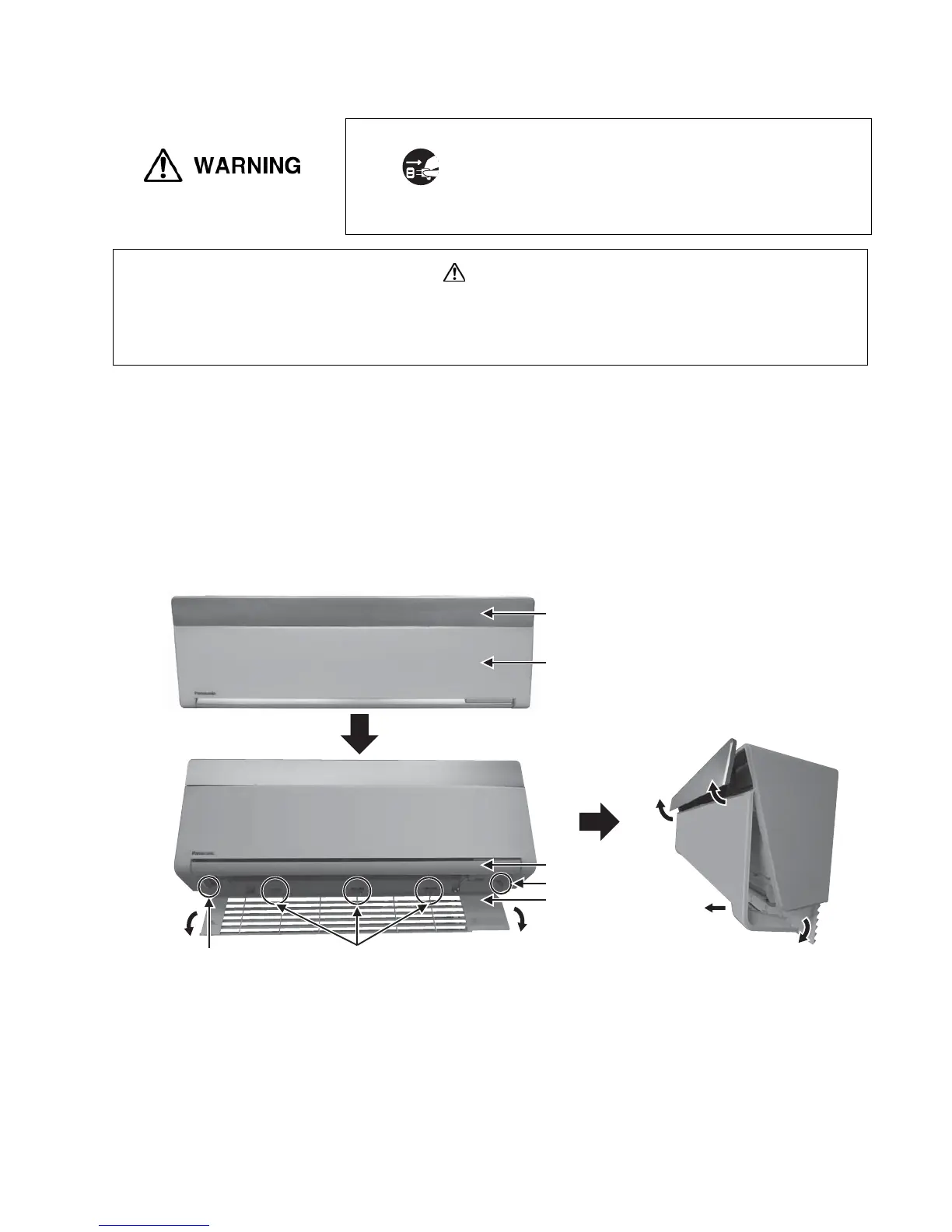
17.1.1 To Open Intake Grille and Remove Front Panel
1. Ensure indicator flap is closed. Detach the intake grille with fingers by pulling the intake grille louver to
downwards. The intake grille hinge is firmly hang to the chassis of the unit.
2. Unscrew the 2 mounting screws from the front panel. Lift up the flap slightly to prevent from blocking the front
panel during detaching. Open the panel until vertically, and pull the front panel towards you to remove the
front panel.
Lower
down
(1) Slightly lift up
(3) Open until vertical
(2) Pull
Indicator Flap
Front Panel
Flap
Intake Grille
HingeScrew
Screw
Note on assembly:
When assemble back, do not over tighten the screws. Over tightening can break the plastic parts.
Disconnect the power plug
Be sure to disconnect the power plug from the outlet before
disassembly or repair of the unit. High Voltage is generated in the
electrical parts area by the capacitor. Ensure that the capacitor has
discharged sufficiently before proceeding with repair work. Failure to
observe this warning could result in electric shock. Be very careful
not to touch the live parts when performing a repair work which
requires power supply or inspecting the circuit. Also, be very careful
of the fan as it can start rotating anytime.

 Loading...