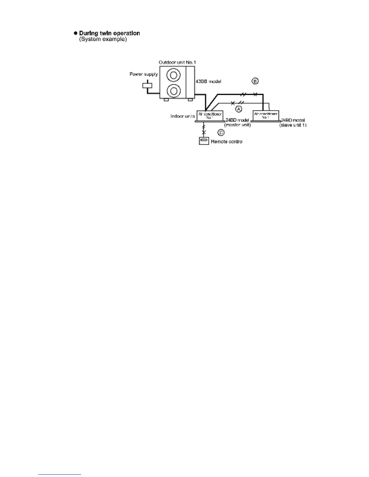
1. The main power is turned on while the transmission wires
between the indoor unit(s) are not connected (open circuit
at section A)
Symptom:
Nothing abnormal appears on the remote control display. If
operation is then started in this condition, the combination
of the 43BB outdoor unit and the 24BD indoor unit (master
unit) will cause abnormal operation to occur.
↓
If operation continues, an abnormality will occur on the
refrigeration cycle and operation will stop.
•
• •
•
Remote control... “CHECK” flashes
•
• •
•
Indoor unit (master)... The LEDs on the printed circuit
board flash and operation stops
•
• •
•
Indoor unit (slave). LED1 on the printed circuit board
illuminates and the unit does not operate at all
•
• •
•
Outdoor unit. The LEDs on the printed circuit board
flash and operation stops
2. The main power is turned on while the power supply wires
between the indoor unit(s) are not connected (open circuit
at section B)
Symptom:
Same as above. If operation continues, an abnormality will
occur on the refrigeration cycle and operation will stop.
↓
•
• •
•
Remote control. “CHECK” flashes
•
• •
•
Indoor unit (master). The LEDs on the printed circuit
board flash
•
• •
•
Indoor unit (slave)... The LEDs on the printed circuit
board do not illuminate and the unit does not operate at
all
•
• •
•
Outdoor unit... The LEDs on the printed circuit board
flash and operation stops
3. The main power is turned on while the remote control
connection cord is not connected (open circuit at section C)
Symptom:
•
• •
•
Remote control unit... Display of “No power supply”
•
• •
•
Indoor unit (master)... LED1 on the printed circuit board
stays illuminated and the unit does not operate
•
• •
•
Indoor unit (slave)... LED1 on the printed circuit board
stays illuminated and the unit does not operate
•
• •
•
Outdoor unit... LED1 on the printed circuit board stays
illuminated and the unit does not operate
Remedy
1. Turn off the main power.
↓
2. Connect the disconnected wires correctly.
↓
3. Turn the main power back on.
↓
4. After 1 minute, start operation using the remote control.
(Indoor units... Operation will start according to the remote
control setting.)
(Outdoor unit... Operation will start after 3-5 minutes.)
If slave units do not operate even after the wiring has been
corrected (automatic addressing is not possible)
1. Check that DIP switches 1 to 4 and DIP switch 8 are all set
to OFF, and then stop operation.
↓
2. Press the ADDRESS RESET button (SW3) at the outdoor
unit for approximately 4 seconds
(The self-diagnosis LEDS 2 to 8 will illuminate in order, and
the system is reset once they are all illuminated.)
The above procedure cannot be used to carry out automatic
address resetting during group control.
79
 Loading...