EasyManua.ls Logo

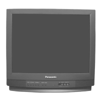
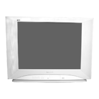
Panasonic CT-20R6E User Manual

Panasonic CT-20R6E
56 pages
To Next Page IconTo Next Page
Page #1 background imageLoading...
Page #1 background image
Panasonic
The service technician is required to read and follow the Safety Precautions” and Important Safety Notice” in this Main Manual.
Service Manual
Color Television
(NA7D)
Main Manual
Copyright 2001 by Matsushita Electric Corporation of
America. All rights reserved. Unauthorized copying
and distribution is a violation of law.
WARNING! This Service Manual is designed for experienced repair technicians only and is not designed for use by the general public.
It does not contain warnings or cautions to advise non-technical individuals of potential dangers in attempting to service a product.
Products powered by electricity should be serviced or repaired only by experienced professional technicians. Any attempt to service
or repair the product or products dealt with in this Service Manual by anyone else could result in serious injury or death.”
Chassis
CT-20R6E AP359
CT-20R6CE AP359
CT-20D11E EP360
CT-20D11DE EP360
CT-2006SE FP360
CT-20G6E DP359
CT-20G6DE DP359
CT-2016SE FP360
Models
ORDER NO. MTNC010303C1
B1
This Service manual is issued as a service guide for the models of the NA7D family listed above. Included in this
manual are a set of schematics, block diagrams, functional descriptions, alignment procedures, disassembly
procedures, and a complete parts list.
Question and Answer IconNeed help?

Do you have a question about the Panasonic CT-20R6E and is the answer not in the manual?

Panasonic CT-20R6E Specifications

General IconGeneral
Screen Size20 inches
Display TypeCRT
Aspect Ratio4:3
TunerAnalog
InputsComposite

Summary

Important Safety Notices

General Safety Guidelines

Covers general precautions, leakage current, X-ray, and high voltage safety.

Service Notes

Component Handling and Replacement

Guides for leadless chips, flat-ICs, and X-ray protection check.

X-Ray Protection Circuit Check

Procedure for checking the X-ray protection circuit.

Receiver Features and Specifications

Control Locations

Receiver Control Panel Overview

Overview of receiver controls and their functions.

Remote Control Button Functions

Explanation of remote control buttons and their operations.

Disassembly and Replacement Procedures

Chassis and CRT Disassembly

Steps for removing the back cover and CRT components.

CRT Replacement Steps

Procedures for handling degaussing coil and ground braid.

Main Components Location

Internal Component Identification

Identification and location of key internal components on the A-Board.

Chassis Service Adjustments

Voltage Checks (B+, High Voltage)

Procedures for confirming B+ and High Voltage levels.

Purity and Convergence Procedures

CRT Yoke and Ring Assembly Setup

Initial setup for yoke, purity, and convergence assemblies.

Vertical Raster Shift Adjustment

Adjusting the vertical position of the raster.

Static Convergence and Purity Steps

Steps for initial, purity, and final convergence adjustments.

Permalloy Corrector Strip Usage

Using a permalloy strip for convergence correction.

Service Mode Operations

Entering, Exiting, and Navigating Service Mode

Procedures for accessing, leaving, and navigating service menus.

Service Adjustments: Picture and Color

Sub-Data, Cut-Off, and Picture Options

Adjusting sub-data, cut-off, and picture options.

Service Adjustments: System Settings

MTS, VCJ, and AFC Adjustments

Adjusting MTS, VCJ, and AFC system parameters.

Electronic Control Adjustments: Video Basics

Sub-Contrast, Sub-Brightness, Tint/Color

Adjusting sub-contrast, sub-brightness, tint, and color.

Electronic Control Adjustments: White Balance

White Balance Adjustments

Adjusting white balance for proper gray scale.

Electronic Control Adjustments: Size, Centering, MTS

Vertical Size, Horizontal Centering, and MTS

Adjusting vertical size, horizontal centering, and MTS.

Electronic Control Adjustments: Separation, Clock, Focus

Stereo Separation and Clock Adjustments

Fine-tuning stereo separation and clock timing.

Focus Adjustment

Adjusting the focus of the picture.

Replacement Parts List

Component Listings

Comprehensive list of capacitors, diodes, ICs, resistors, and more.

General Information

Abbreviations Guide

Guide to abbreviations used for resistors and capacitors.

C-Board Schematics and Voltages

C-Board Schematic and Voltage Data

Provides the C-Board schematic and voltage measurements.

A-Board Schematics

Left and Right Portion Schematics

Detailed schematics for the left and right portions of the A-Board.

A-Board PCB Layout

A-Board Voltage Measurements

Voltage Chart and Measurement Notes

A-Board voltage chart and essential measurement notes.

A-Board Waveform Measurements

Waveform Analysis Guide

Guide for analyzing and measuring waveforms.

Related product manuals