EasyManua.ls Logo

Panasonic CT-27E13G User Manual

Panasonic CT-27E13G
95 pages
To Next Page IconTo Next Page
Page #1 background imageLoading...
Page #1 background image
MTNC030731A1
B05
Color Television
CT-27E13G / CT-27E33G / CT-32E13G / CT-32E33G / CT-
36E13G / CT-36E33G
NA10
This simplified service manual is issued to add listed models to the
main service manual order No. MTNC030623C1(CT-25L8G). A
complete parts list and schematics are included in this simplified
service manual. Please file and use this simplified servicemanual
together with the main service manual order No. MTNC030623C1(CT-
25L8G).
Copyright 2003 Matsushita Electric Corporation of America. All
rights reserved. Unauthorized copying and distribution is a
1
MC-Service
Question and Answer IconNeed help?

Do you have a question about the Panasonic CT-27E13G and is the answer not in the manual?

Panasonic CT-27E13G Specifications

General IconGeneral
Screen Size27 inches
Display TypeCRT
Aspect Ratio4:3
InputsComposite, RF
Speakers2
ResolutionStandard Definition
Audio OutputMono

Summary

Service Manual - Color Television

1. Safety Precautions

General Guidelines and Warnings

Essential safety guidelines for servicing, including handling high-voltage parts and picture tubes.

2. Service Notes

Chip Component Handling and Removal

Techniques for servicing leadless chip components and flat ICs, including removal and installation.

3. EEPROM Replacement

4. About Lead-Free Solder (PbF)

5. Receiver Feature Table

6. Board Description Table

7. TV Location of Controls

8. Location of Controls (Remote)

Quick Reference Control Operation

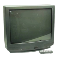
An overview of remote control buttons and their immediate functions.

9. Disassembly for Service

Back Cover Removal Procedure

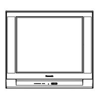
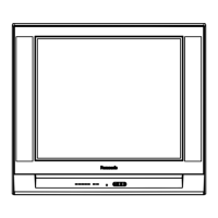
Step-by-step guide for safely removing the rear cabinet cover.

10. Chassis Service Adjustment Procedures

11. Service Adjustments (Mechanical Controls)

11.1. Dynamic Convergence Adjustment (36" Models)

Procedure for adjusting dynamic convergence on 36-inch models for optimal picture geometry.

12. Service Mode (Electronic Adjustments)

Quick Entry to Service Mode

Method to access service mode using the remote control without opening the cabinet.

13. Service Adjustments (Electronic Controls)

13.1. Sub-Brightness and Contrast / Service DAC Adjustment

Adjusting brightness and contrast using DAC for proper picture settings.

13.2. PIP Sub-contrast (PCONT) Adjustment

Procedure to adjust the sub-contrast for Picture-in-Picture (PIP) signals.

13.4. Color Output Adjustment (COLOR, TINT, B-Y_G)

Adjusting color and tint parameters for accurate color reproduction.

13.6. Deflection Adjustments

13.6.1. H-Center Adjustment

Procedure to align the horizontal position of the picture on the CRT screen.

13.6.2. Horizontal Width Adjustment (H-WID)

Adjusting the horizontal width of the picture for optimal display.

14. Identification of Components

14.1. Chassis Components Identification

Locating and identifying key components on the main TV chassis.

14.1.1. C-Board Chassis Component Layout

Diagram showing the component layout on the C-Board.

14.1.3. Y-Board Chassis Component Layout

Diagram showing the component layout on the Y-Board.

14.1.4. A-Board Chassis Component Layout

Diagram showing the component layout on the A-Board.

16. Conductor Views

16.1. A-Board Printed Circuit View

Layout of the A-Board's printed circuit showing conductor paths.

17. Block Diagrams

17.1. Video Signal Block Diagram

Diagram illustrating the flow of the video signal through the TV.

18. Schematics

18.1. English Schematic Notes

Key to understanding schematic symbols and notes for accurate interpretation.

19. Parts Location

18.16. Voltages

List of voltage test points and their nominal values.

20. Parts List

20.1. Parts List Notes and Abbreviations

Explanation of abbreviations and safety notes for the parts list.
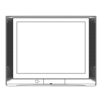
A-Board Waveform Diagrams

Related product manuals