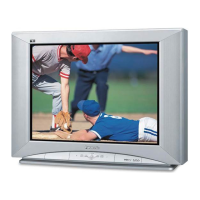
This document is a service manual for the Panasonic Color Video Monitor CT-S1390Y, G15M Chassis.
Function Description
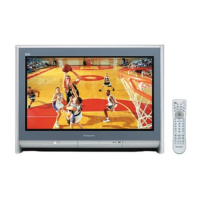
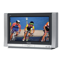
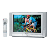
The Panasonic CT-S1390Y is a color video monitor designed for displaying video signals. It supports both standard video and S-Video inputs, with loop-through capabilities for connecting to other devices for monitoring and recording. The monitor includes audio input/output terminals, allowing for integrated audio monitoring. Front panel controls provide user access to essential display adjustments such as sharpness, contrast, brightness, tint, color, and volume, along with input selection and a "Normal" button to reset picture control levels to factory defaults.
Important Technical Specifications
Power Source: AC 120V, 60Hz
MAX Amps: 1.4A
Picture Tube: 13" Diagonal, 90-degree deflection
Speaker Output: 1.5W (10% THD)
Resolution: 420 TV lines (Horizontal)
Dimensions:
- Width: 14 3/8" (365 mm)
- Depth: 15 15/32" (393 mm)
- Height: 12 17/32" (318.5 mm)
Weight: 28.2 lbs. (12.8 kg)
Operating Temperature: 32°F to 95°F (0°C to +35°C)
Operating Humidity: 20% to 80% (without dew on the surface of each part)
Safety Regulations: UL1410 Listed
EMC Regulations: Complied with FCC rules, Part 15
Video/Audio Terminals (LINE A/LINE B):
- Video Input: 1.0Vp-p, 75Ω or High impedance (Auto), BNC type connector
- Video Through Out: Automatic Termination Opener, BNC type connector
- Audio Input: 0.5Vrms, 22kΩ or more, phono type connector
- Audio Through Out: Phono type connector
- S-Video Input: Y signal 1.0Vp-p, C signal 0.285Vp-p, 75Ω or High impedance (Manual), MINI DIN 4P type connector
- S-Video Output: Y signal 1.0Vp-p, C signal 0.285Vp-p, 75Ω or High impedance (Manual), MINI DIN 4P type connector
Usage Features
The monitor offers flexible connectivity with two sets of LINE A and LINE B inputs, each supporting both standard video (BNC) and S-Video (4-pin MINI DIN) signals, along with RCA phono audio inputs.
- Input Selection: A front panel switch allows users to toggle between LINE A and LINE B inputs. Rear panel selectors for LINE A also allow switching between S-Video and Video input for LINE A.
- S-Video Impedance Switch: A rear switch allows setting the S-Video output impedance to 75Ω or HI-Z, important when connecting to other devices.
- Loop-Through Functionality: Both Video (BNC) and S-Video terminals support loop-through, enabling the signal to be passed to other monitors or recording devices while simultaneously being displayed.
- Front Panel Controls:
- Power Switch: ON/OFF control.
- Input Selector: Selects between LINE A and LINE B signals.
- Operation Indicator: Lights up when power is ON, flashes when adjusting controls, and flashes twice when the Normal Button is pressed.
- Normal Button: Resets picture control levels to factory-set mid values.
- Sharpness Control: Adjusts picture sharpness (Soft to Sharp).
- Contrast Control: Adjusts picture contrast (Decrease to Increase).
- Brightness Control: Adjusts picture brightness (Dark to Bright).
- Tint Control: Adjusts picture tint (Red to Green).
- Color Control: Adjusts color intensity (Low Color to High Color).
- Volume Control: Adjusts audio output volume (Min. to Max.).
Maintenance Features
The service manual provides comprehensive information for maintenance and repair, emphasizing safety precautions due to high voltage components.
- Safety Precautions: Detailed guidelines include using an isolation transformer, observing original lead dress, proper installation of protective devices, resistance checks for B+ lines, and discharging the picture tube anode before handling. Warnings about X-Radiation and potential shock hazards are highlighted.
- Leakage Current Checks: Both cold and hot leakage current checks are outlined to ensure electrical safety after servicing.
- High Voltage Check: Procedure for measuring high voltage (24.5kV ± 1.5kV) to prevent premature component failure and X-Radiation.
- Radiation Safety Circuit Test: A final check procedure to ensure the X-Ray protection circuit functions correctly.
- Circuit Explanation: Description of the Horizontal Oscillator Disable Circuit, which monitors high voltage and beam current to activate X-Ray protection if levels exceed specified limits.
- Disassembly Instructions: Step-by-step guide for disassembling the rear cover, cabinet, P.C. boards (A-P.C., W-P.C., U-P.C., P-P.C., L-P.C.), and picture tube, with warnings about careful handling and electrical shock risks.
- Self Check Functions: A diagnostic mode activated by simultaneously pressing "Color Up" and "Brightness Up" buttons. It displays error codes (H90, H35, H55, H56, H57) to indicate communication abnormalities between microprocessors, video chroma jungle circuit, or abnormal voltage/load on positive voltage lines.
- Market Service Mode: A special mode for making various adjustments via front panel buttons, including Sub-Adjustment (Sub Color, Sub Tint, Sub Bright, Sub Contrast), White Balance Adjustment (RGB R-CUT, G-CUT, B-CUT, RGB BRIGHT, RGB B-DRIVE, R-DRIVE, SUB BRIGHT), and H/V Amplitude Adjustment (H-V H-POS, H-V V-HET). These adjustments are necessary after memory or picture tube replacement, or after replacing deflecting coil circuit components.
- Measurements and Adjustments:
- B+ Voltage Adjustment: Procedure for checking and adjusting various B+ voltages using a digital voltmeter.
- Purity Adjustment: Detailed steps involving degaussing, inputting a crosshatch pattern, rough convergence, and adjusting purity magnets and deflection yoke for optimal green, red, and blue screen purity.
- Convergence Adjustment: Procedure for adjusting static and dynamic convergence using four-pole and six-pole magnets, and tilting the deflection yoke.
- Focus Adjustment: Adjusting the focus control on the FBT (Flyback Transformer) for the sharpest picture.
- Circuit Board Layouts: Diagrams showing the arrangement of components on the W-P.C., L-P.C., P-P.C., and U-P.C. boards.
- Terminal Guides: Pinout descriptions for key ICs (IC001 MN152811HYG, IC301 AN5163K), transistors, and diodes.
- IC Function of Terminal and Equivalent Circuit: Detailed functions of each pin for the main ICs.
- Block Diagrams: Visual representation of the monitor's internal signal flow.
- Schematic Notes and Waveforms: Important notes for understanding the schematic diagram, including component specifications and test point waveforms.
- Parts List: A comprehensive list of replacement parts, with critical safety components highlighted in bold type, emphasizing the use of manufacturer-specified parts.