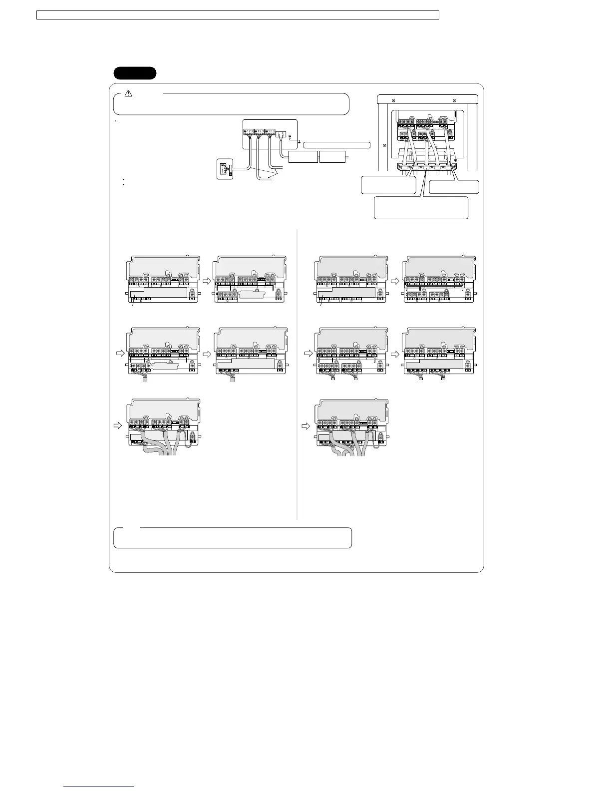
Wiring
Do not turn ON the safety breaker until all work
is completed.
(1) Strip the insulation from the wire (20 mm).
(2) Connect the connection wires between the
indoor and outdoor units so that the
terminal numbers match. Tighten the terminal
screws securely. We recommend
a flathead screwdriver be used to tighten
the screws. The screws are packed with
the terminal board.
Power supply cord : 3×2.5mm
2
or more
Connecting cord between indoor and outdoor : 4×1.5mm
2
(3) Pull the wire and make sure that it does not disconnect.
Then fix the wire in place with a wire stop.
(1) Remove the service lid, and it should be as in Figure (A).
First push up the cover as shown in Figure (B), then connect room C (Figure (C)).
Be sure to connect from room C.
(2) After room C is connected, replace the cover (Figure (D)).
(3) Connect room A, B and power supply wires (Figure (E)).
(4) When connecting the power supply wires to rooms A and B, route the wires so that no force
will be applied to the lid, which may otherwise be deformed. (Figure (E))
(1) Remove the service lid, and it should be as in Figure (A).
First push up the cover as shown in Figure (B), then connect room C,D (Figure (C)).
Be sure to connect from room C,D.
(2) After room C and D are connected, replace the cover (Figure (D)).
(3) Connect room A, B and power supply wires (Figure (E)).
(4) When connecting the power supply wires to rooms A and B, route the wires so that no force
will be applied to the lid, which may otherwise be deformed. (Figure (E))
Do not use tapped wires, stand wires, extensioncords, or starbust connections, as they may cause overheating,
electrical shock, or fire.
WARNING
Room
A
Room A
To room B
To room C
Room
C
Room
B
Outdoor unit
Indoor unit
Safety breaker
20A
Ground fault
interrupter
50Hz 220-240V
Be sure to use the correct circuits.
245 IEC57 (H05RN-F)
(A) (B)
(C) (D)
Cover
(A) (B)
(C) (D)
Cover
Shape the wires so that there
is no lifting of the service
hatch or other structural parts.
Secure the branch wiring firmly using the 4 included
screws, as shown in the figure.
Secure firmly, making sure no outside pressure is
exerted on the terminals.
Use the specified wires and
connect them securely.
For CU-3E23CBPG, follow the procedure below to connect the wires. For CU-4E27CBPG, follow the procedure below to connect the wires.
(When connecting 3 or more rooms)
This air conditioner must be earthed.
For earthing, follow the applicable local standard for electrical installations.
Earth
(E)
(E)
78
CS-ME7CKPG / CS-ME10CKPG / CS-ME12CKPG / CS-ME14CKPG / CS-ME18CKPG / CU-2E15CBPG / CU-2E18CBPG / CU-3E23CBPG / CU-4E27CBPG