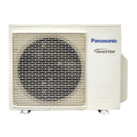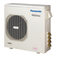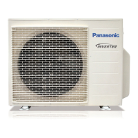
Do you have a question about the Panasonic CU-3MC200KE and is the answer not in the manual?
| Brand | Panasonic |
|---|---|
| Model | CU-3MC200KE |
| Category | Air Conditioner |
| Language | English |
Detailed control functions via the remote unit, including mode and fan speed.
Operational features and controls specific to the indoor unit.
Protection and operational controls managed by the outdoor unit.
Physical size and layout details for the CS-MC90KE model.
Physical size and layout details for the CU-MC140KE model.
Physical size and layout details for the CU-MC180KE model.
Physical size and layout details for the CU-3MC200KE model.
Diagram illustrating the refrigerant flow for specific model combinations.
Diagram illustrating the refrigerant flow for specific model combinations.
Diagram illustrating the refrigerant flow for specific model combinations.
Electrical system overview showing component connections for specific models.
Electrical system overview showing component connections for specific models.
Electrical system overview showing component connections for specific models.
Detailed electrical wiring schematics for specific model combinations.
Detailed electrical wiring schematics for specific model combinations.
Detailed electrical wiring schematics for specific model combinations.
How to operate the unit in cooling mode and its safety controls.
Details on soft dry mode operation, fan speed, and safety controls.
How the unit automatically selects operation modes based on conditions.
Functionality of automatic restart after power interruptions.
Methods for adjusting indoor fan speed in different operating modes.
How to control the direction of airflow using auto and manual settings.
List of included accessories required for unit installation.
Guidelines for choosing optimal indoor and outdoor unit installation locations.
Visual guide illustrating the installation process and component connections.
Operation and port configuration for the liquid side 3-way valve.
Operation and port configuration for the gas side 3-way valve.
Points to inspect on the indoor unit's electronic control board.
Step-by-step guide for removing the indoor fan motor.
Procedure for removing the cross flow fan assembly.
How to control solenoid valves using auto/manual switches.
Procedures for resetting and changing remote control transmission codes.
Steps to diagnose issues using temperature, pressure, and current readings.
Methods for identifying compressor faults and their symptoms.
Graphs showing thermostat operation and temperature settings for cooling/soft dry.
Performance graphs showing capacity, current, and pressure vs. temperature.
Diagram showing the assembly breakdown of the CS-MC90KE indoor unit.
Diagram showing the assembly breakdown of the CU-MC140KE outdoor unit.
Diagram showing the assembly breakdown of the CU-MC180KE outdoor unit.
Diagram showing the assembly breakdown of the CU-3MC200KE outdoor unit.
List of replaceable parts and their corresponding part numbers for CS-MC90KE.
List of replaceable parts and their corresponding part numbers for CU-MC140KE.
List of replaceable parts and their corresponding part numbers for CU-MC180KE.
List of replaceable parts and their corresponding part numbers for CU-3MC200KE.
List of electronic components and their part numbers for CS-MC90KE.
List of electronic components and their part numbers for CU-MC140KE/CU-3MC200KE.


 Loading...