—9—
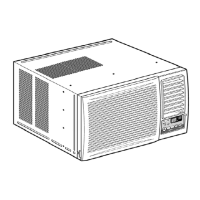
2.3.3 CAPACITOR
1. Remove the control box. (Refer to section 2.1.3)
2. Remove the knobs and the screw which fasten
control panel from control box.
3. Remove the screw which located in the front.
4. Open the bottom side of control box.
5. Remove the screw and the clamp which fastens
the capacitor.
6. Disconnect all the leads of capacitor terminals.
7. Re-install the components by referring to the
removal procedure, above. (See Figure 11)
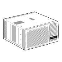
2.3.4 POWER CORD
1. Remove the control box. (Refer to section 2.1.3)
2. Open the control box. (Refer to section 2.3.3)
3. Disconnect the grounding screw from the control
box.
4. Disconnect the 2 receptacles.
5. Remove a screw which fastens the clip cord.
(See Figure 12)
6. Remove the power cord.
7. Re-install the component by referring to the above
removal procedure, above.
(Use only one ground-marked hole for ground
connection.)
8. If the supply cord of this appliance is damaged, it
must be replaced by the special cord. (The
special cord means the cord which has the same
specification marked on the supply cord attached
at the unit.)
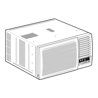
2.3.5 THERMISTOR
1. Remove the control box. (Refer to section 2.1.3)
2. Open the control box. (Refer to section 2.3.3)
3. Disconnet the thermistor terminals from main
P.W.B assembly.
4. Remove the thermistor.
5. Re-install the components by refereing to the
above removal procedure. (See Figure 13)
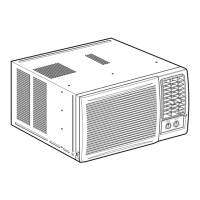
2.3.6 SYNCHRONOUS MOTOR
1. Remove the control box. (Refer to section 2.1.3)
2. Unfold the control box. (Refer to section 2.3.3)
3. Remove the crankshaft.
4. Disconnect all the leads of the synchronous
motor.
5. Remove the 2 screws which fasten the
synchronous motor. (See Fig. 14)
6. Re-install the components by referring to the
removal procedure, above.
Figure 12
Figure 11
Figure 13
Figure 14
 Loading...