POWER
CN309
OP1
3P (Yellow)
DC12V
EP valve
Balance valve
Intake valve
Output valve
5P (Black)
Indoor control PCB
Signal output cables
(short)
(Supplied part ③)
CN81
3WAY
Optional parts
Solenoid valve
kit or gas pipe
valve kit
CN002
POWER
3P (White)
[AC Power Input]
CN001
OPTION/3WAY
6P (White)
CN003
9P (Red)
[Solenoid valve output]
Protective ground screw
Protective ground screw
Protective ground screw
Solenoid valve control PCB
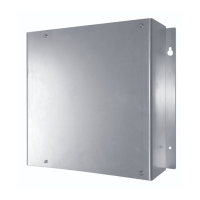
Optional board box
Indoor unit
Power cables (2 core)
(Supplied part ②)
Models where installation is possible in indoor unit electrical box
POWER
CN309
OP1
3P (Yellow)
DC12V
EP valve
Balance valve
Intake valve
Output valve
5P (Black)
Indoor control PCB
Signal output cables
(long)
(Supplied part ③)
CN81
3WAY
Optional parts
Solenoid valve
kit or gas pipe
valve kit
CN002
POWER
3P (White)
[AC Power Input]
CN001
OPTION/3WAY
6P (White)
CN003
9P (Red)
[Solenoid valve output]
Protective ground screw
Protective ground screw
Protective ground screw
Solenoid valve control PCB
Optional board box
Indoor unit
Power cables (3 core)
(Supplied part ②)
Normal installation
Solenoid Valve Installation (Electric) and Service Instructions
1. Safety Precautions
3. Wiring Diagram
The connected solenoid valve is a solenoid valve kit, or a gas pipe valve kit.
Controller(CZ-CAPE2)
Optional board box
screws 4x10
(2 locations)
OPTION/3WAY
(CN001)
6P White
POWER
(CN002)
3P White
6P White
screw 4x4
5P Black
CN003
9P Red
Spacers (4 locations)
Optional parts
9P Red
Solenoid valve
kit or gas pipe
valve kit
Protective ground screw
for
power cable (3 core)
Protective ground screw
for solenoid valve kit or gas pipe valve kit
4. Installation Procedures
Note: See the reverse side for procedures for installation on various indoor units.
Models where installation is possible in indoor unit electrical box
1. Install the spacers for the solenoid valve control PCB in the electrical box.
2. Wire according to the following procedure.
3. When you have finished wiring work, check to be sure that there are no nipped portions in the wiring.
Connect the 3P white connector of power cable(2 core) (Supplied part ②) to POWER (CN002) on
the solenoid valve control PCB.
Connect the 3P yellow connector to OP1 (CN309) on the indoor control PCB.
Connect the 6P white connector of Signal output cable (the short cable) (Supplied part ③) to OPTION/3WAY (CN001) on
the solenoid valve control PCB.
Connect the 5P black connector to 3WAY (CN81) on the indoor control PCB.
Connect the connector from the solenoid valve kit or gas pipe valve kit (9P red) to the 9P red connector (CN003) on the solenoid valve
control PCB.
Connect the ground wire of the solenoid valve kit or gas pipe valve kit to the indoor unit
using the screw and washer (supplied part ⑦).
* For the connecting location, refer to the indoor unit installation instructions.
Power cable (2 core) (Supplied part ②)
3P Yellow
To indoor control PCB
OP1(CN309)
3P White
Signal output cable (short cable) (Supplied part ③)
5P Black
To indoor control PCB
3WAY (CN81)
6P White
CN003
9P Red
OPTION/3WAY
(CN001)
6P White
POWER
(CN002)
3P White
Optional parts
Solenoid valve
kit or gas pipe
valve kit
9P Red
① Solenoid Valve Control PCB
⑧ Nylon clamp(F7,F14)
3P Yellow
3P White
③ Signal output cables(long/short)
5P Black
6P White
② Power cables (3 core/2 core)
3P Yellow
3P White
⑤ Fastening screws
Screw 4x4-2 (1 pc.)
Screw 4x10⁻² (2 pcs.)
④ Optional board box
⑦ Protective ground screw
for indoor unit
Screw 4x8-3
Washer
⑥ Cable tie (4 pcs.)
Connect to the indoor control PCB with power cable(2 core/3 core) (Supplied part ②) and Signal output cable (Supplied part ③)
Signal output cable (long/short) (Supplied part ③)
3P Yellow
3P White
Power cable (3 core/2 core) (Supplied part ②)
The following is intended for the person responsible for installing or servicing the Solenoid Valve
Controller. Before conducting installation or electrical work, be sure to carefully read these
“Safety Precautions”. Follow instructions exactly in all installation or electrical work.
The precautions given in this manual consist of specific “Warnings” and “Cautions”. They provide
important safety related information and are important for your safety, the safety of others, and
troublefree operation of the system. Be sure to strictly observe all safety procedures. The labels and
their meanings are as described below.
This symbol refers to a hazard or unsafe procedure or practice which can result in
severe personal injury or death.
Warning
Caution
This symbol refers to a hazard or unsafe procedure or practice which can result in
personal injury or product or property damage.
Warning
Be sure to arrange installation at the dealer where the system was purchased or use a professional
installer.
Leaks, electric shock or fire may result if an inexperienced person performs any installation or wiring
Be sure to turn off the power source circuit breaker of the unit before installation or wiring.
High electrical voltages used in the unit may cause electric shock.
procedures incorrectly.
Only a qualified electrician should attempt to install this system, in accordance with the provisions of
the Technical standards for Electrical Installations, local regulations for indoor wirings and these
“Installation (Electric) and Service Instructions”. Be sure to use a dedicated electrical circuit.
Insufficient electrical circuit capacity may cause electric shock or fire.
Use the specified cables (type and wiring diameter) for the electrical connections, and securely connect
the cables. Run and fasten the cables securely so that external forces or pressure placed on the cables
will not be transmitted to the connection terminals. Overheating or fire may result if connections or
attachments are not secure.
Install in a location that is fully strong enough to support the weight of the unit. If it is not strong enough,
the unit may fall, resulting in injury.
Ventilate the work area if cooling gas leaks during installation. Poisonous gas can result if cooling gas
comes into contact with fire.
After installation, check to be sure that there are no gas leaks.
Poisonous gas can result if cooling gas leaks into the room and comes into contact with a fan heater,
stove, range, or other source of fire.
Caution
Do not install in a location subject to leakage of flammable gasses.
Fire can result if gas builds up around the unit.
2. Supplied Parts
1. Install the solenoid valve control PCB in the optional board box with the following procedure.
2. Wire according to the following procedure.
3. When you have finished wiring work, secure the cover of the optional board box with the supplied screw (4x4)
Install the board spacers in the holes in the base of the optional board box.
Note: When you do so, be careful of the direction of the solenoid valve conrol PCB(see following figure).
Attach the optional board box to the unit with the supplied screws(4x10).
Models without space inside electrical box
Connect the 3P yellow connector of power cable (Supplied part ②) to OP1 (CN309) on the indoor control PCB.
Connect the 5P black connector of signal output cable (Supplied part ③) to 3WAY (CN81) on the indoor control PCB.
Connect the ground wire of the power cables (3 core) to the indoor unit using the screw and washer (supplied part ⑦).
* For the connecting location, refer to the indoor unit installation instructions.
* When you use the power cables (2 core) for installing inside electrical box, ground connection is unnecessary.
Connect the ground wires of the power cables and solenoid valve kit or gas pipe valve kit to the optional board box.
* When you use the power cables (2 core), only connect the ground wire of the solenoid valve kit or gas pipe valve kit.
Connect the 3P white connector of power cable(Supplied part ②) to POWER(CN002) on the
solenoid valve control PCB.
Connect the 6P white connector of signal output cable(Supplied part ③) to OPTION/3WAY(CN001) on the
solenoid valve control PCB.
Connect the connector from the solenoid valve kit or gas pipe valve kit (9P red) to the 9P red connector (CN003) on the
solenoid valve control PCB.
Fasten the wires to the optional board box with the cable ties (supplied part ⑥)
Note: When you do so, check to be sure that there are no nipped portions in the wiring.
Use the long cables and 3 core cables
when the solenoid valve controller is
installed outside the indoor unit.
Printed in Japan 85464369377012
To indoor control PCB
OP1(CN309)
To indoor control PCB
3WAY (CN81)