EasyManua.ls Logo

Panasonic CZ-64ESMC2 User Manual

Panasonic CZ-64ESMC2
142 pages
To Next Page IconTo Next Page
Page #1 background imageLoading...
Page #1 background image
Save these instructions!
Conservez précieusement ces instructions !
Diese Anleitung aufbewahren!
Conservare le presenti istruzioni!
Guarde estas instruções!
Φυλάξτε αυτές τις οδηγίες!
¡Guarde estas instrucciones!
CZ-64ESMC2
85464369350010
System Controller for Split System Air
Conditioner
Contrôleur de système pour climatiseur d’air à
deux blocs
Systemsteuerung Split-Klimagerät
Controllore di sistema per condizionatore
d’aria a sistema Split
Controlador do sistema de ar condicionado
com sistema distribuído
Ελεγκτής συστήματος για κλιματιστικο με
εσωτερική και εξωτερική μονάδα
Controlador de sistema para acondicionador
de aire tipo separado
INSTALLATION INSTRUCTIONS
INSTRUCTIONS D’INSTALLATION
BEDIENUNGSANLEITUNG
ISTRUZIONI DI INSTALLAZIONE
INSTRUÇÕES DE INSTALAÇÃO
ΟΔΗΓΙΕΣ ΕΓΚΑΤΑΣΤΑΣΗΣ
INSTRUCCIONES DE INSTALACIÓN
EN
FR
DE
IT
PT
GR
ES
CZ-64ESMC2eng.indd1CZ-64ESMC2eng.indd1 2010/12/2416:58:322010/12/2416:58:32

Table of Contents

Other manuals for Panasonic CZ-64ESMC2

Question and Answer IconNeed help?

Do you have a question about the Panasonic CZ-64ESMC2 and is the answer not in the manual?

Panasonic CZ-64ESMC2 Specifications

General IconGeneral
ModelCZ-64ESMC2
CategoryController
I/O Points64
Power Supply24V DC
Input TypeDC
Output TypeRelay
Communication PortsRS-232, RS-485
Operating Temperature0°C to 55°C
Storage Temperature-25°C to 75°C
Instruction Execution Speed0.1 µs per basic instruction

Summary

Installation Instructions

Safety and Requirements

Installation Location Guidelines

Guidance on selecting an appropriate installation site for the controller.

Electrical Installation Requirements

Specifies electrical codes and wiring qualifications needed for installation.

General Safety Precautions

Important safety precautions for operating the system controller.

General Installation Guidelines

General Product Information

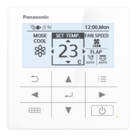
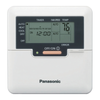
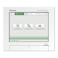
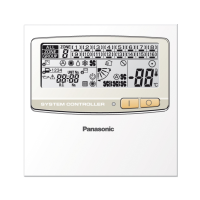
Overview of the controller, parts, and initial setup notes.

Installation Site Selection Criteria

Recommendations for choosing the optimal location to install the controller.

Controller Mounting Procedure

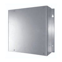
Steps and precautions for physically installing the system controller.

System Controller Overview

Physical Dimensions and Layout

Detailed diagram showing the controller's dimensions and component layout.

Installation Procedure Details

Normal Mounting Method

Instructions for mounting the system controller in the standard manner.

Flush Mounting Method

Steps for flush mounting the system controller into a wall opening.

Electrical Terminal Layout

Basic Wiring Connections

Identifies terminals for power supply and inter-unit control wiring.

Remote Monitoring Terminals

Details terminals for input and output signals for remote monitoring.

Basic Wiring Diagram

System Wiring Configuration

Illustrates wiring between outdoor units, controllers, and remotes.

Address and Switch Settings

Address Switch Configuration

Setting the address switches on the PCB for unit identification.

Accessing the Control Unit PCB

Guide on how to open the controller to access the Printed Circuit Board.

System Controller Switch Functions

SW1 Switch Settings

Explains the various functions controlled by SW1 switches.

SW2 Switch Settings

Description of SW2 switches for auxiliary and indication functions.

Mode Setting Configuration

Central/Remote Control Mode

Selects between central control and remote control operation modes.

ALL/ZONE Mode Selection

Configures control for all units or specific zones.

Zone Registration Procedures

Remote Controller Zone Registration

Steps to register zones using the remote controller.

System Controller Zone Registration

Manual zone registration process using the system controller.

Automatic Zone Registration

Automated method for registering zones via the system controller.

Central Address Overlap Check

Overlap Checking Procedure

Guide to verify for conflicting central address assignments.

Operational Checks

Memory Back Up Switch Verification

Verifies the setting of the memory back up switch on the PCB.

Test Run Procedure

Steps to perform the initial test run and verify unit addresses.

System Configuration Examples

Systems Without Inter-Unit Link

Examples of system setups lacking communication links between units.

Systems With Inter-Unit Link

Examples of system setups featuring communication links between units.

Related product manuals