7
EN
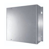
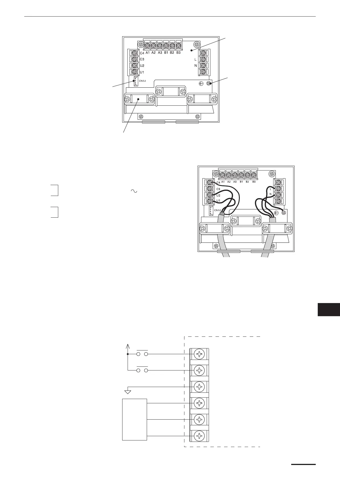
Layout of electrical terminals
Earth for
power wiring
Clamp for electrical wiring
Connector (CN02) for
schedule timer (optional)
Fig. 3
P.C. board
SYSTEM CONTROLLER
DC24V
COM
DC voltage pulse
Photocoupler input
Allowable contact voltage
and current : 24 V , 10 mA
Pulse width : 300 ms or more
No-voltage a-contact
static output
Allowable contact voltage
and current : 30 V , 0.5 A
Digital
Input
A1
A2
A3
B1
B2
B3
How to connect electrical wiring
1) Basic wiring
N:
Power supply (220 – 240 V 50/60 Hz)
L:
U1:
Inter-unit control wiring. (Low voltage)
(Use shielded wiring)
U2:
C3: Reserve
C4: Earth for inter-unit control wiring
2) Terminals for remote monitoring
A1: Input for turning on air conditioners concurrently.
A2: Input for turning off air conditioners concurrently.
A3: Common input for turning air conditioners on or off.
B1: On operation state indicator output.
B2: Alarm indicator output.
B3: Common indicator output.
CZ-64ESMC2eng.indd7CZ-64ESMC2eng.indd7 2010/12/2416:58:332010/12/2416:58:33
 Loading...