9
When there are multiple indoor units
T10R1 R2
CN03
1 2
R1 R2 R1 R2
Indoor unit
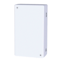
Example
WLAN Adaptor
Remote controller
wiring
(eld supply)
● No polarity
Wired
remote
controller
(main unit)
Communication lines
(1.9 m total length)
Indoor unit Indoor unit
Terminals
for remote
controller
wiring
T10 connector
Example of standard installation
1
Connect the communication lines to the indoor unit.
Example: With a 4-way cassette indoor unit
Remote controller terminal board
Thread the leads through the
catches in the electrical box.
Fix in place with the included
clampers
T10 connector
● Fix the communication lines in place with the included clampers*.
* Make sure the clampers hold the parts coated in white.
● Lead wires* with crimper terminals should be connected to the remote
controller terminal board. Lead wires* with connectors should be connected to
the T10 connector.
* There may be left over lead wires depending on the type of indoor unit. Tie
back left over lead wires with the included clampers.
* The lead wires with crimper terminals have no polarity.
1_WLAN Adaptor_CZ-CAPWFC1_En.indd 9 2018/12/27 18:13:49
 Loading...