15
3. HOW TO INSTALL THE OUTDOOR UNIT
3-1. Installing the Outdoor Unit
● Use concrete or a similar material to make the base, and
ensure good drainage.
● Ordinarily, ensure a base height of 5 cm or more. If a drain
pipe is used, or for use in cold-weather regions, ensure a
height of 15 cm or more at the feet on both sides of the unit.
(In this case, leave clearance below the unit for the drain
pipe, and to prevent freezing of drainage water in cold-
weather regions.)
● See Fig. 3-1 for the anchor bolt dimensions.
● "ESURETOANCHORTHEFEETWITHANCHORBOLTS-)N
addition, use anchoring washers on the top side.
(Use large square 32 × 32 SUS washers with nominal
diameter of 8.) (Field supply)
Unit: mm
18
619
799
570
510.6
394
176.6
61.6
22
299
121
31
45.3
42.8
42.8
18.5
330
355
33
105
69
!IR$ISCHARGE
Air Intake
Air Intake
$RAINPORT
(3-
ø
20)
(OLEFORDRAINSOCKET
(
ø
20)
$RAINSOCKECT&IELDSUPPLY
Fig. 3-1
3-2. Drainage Work
The drain water will be discharged from the unit during heating
or defrosting operation mode.
Select an appropriate location with good drainage system.
(In winter, there is a risk of slipping caused by freezing
depending on the installation location.)
● Ensure a height of 15 cm or more at the feet on both sides of
the unit.
● 0RECAUTIONSFOR)NSTALLATIONIN(EAVY3NOW!REAS
The platform should be higher than the maximum snow depth.
(In this case, leave clearance below the unit for the drain
pipe, and to prevent freezing of drainage water in cold-
weather regions.)
● When using a drain pipe, install the drain socket (field
supply) onto the drain hole. Seal the other drain hole with the
rubber cap (field supply). For details, refer to the instruction
manual of the drain socket (field supply).
After completing the installation work of the drain socket,
make sure that the water does not leak from any part of
connection.
● In cold regions (where the outdoor temperature can drop to
below 0° for 2 to 3 consecutive days), the drain water may
freeze and may prevent the fan from operating. For this
case, do not use the drain elbow.
3-3. Routing the Tubing and Wiring
● See Fig. 3-1.
CAUTION
●
Route the tubing so that it does not contact the
compressor, panel, or other parts inside the unit. Increased
noise will result if the tubing contacts these parts.
●
When routing the tubing, use a tube bender to bend the tubes.
● In cold-weather regions, in order to prevent drainage
water from freezing, do not install the drain socket cap.
Also take steps to prevent water from accumulating
around the unit.
4. ELECTRICAL WIRING
4-1. General Precautions on Wiring
"EFOREWIRINGCONFIRMTHERATEDVOLTAGEOFTHEUNITAS
shown on its nameplate, then carry out the wiring closely
following the wiring diagram.
WARNING
(2) This equipment is strongly recommended to be
INSTALLEDWITH%ARTH,EAKAGE#IRCUIT"REAKER%,#"
OR2ESIDUAL#URRENT$EVICE2#$/THERWISEITMAY
cause electrical shock and fire in case of equipment
breakdown or insulation breakdown.
%ARTH,EAKAGE#IRCUIT"REAKER%,#"MUSTBE
incorporated in the fixed wiring in accordance with the
WIRINGREGULATIONS4HE%ARTH,EAKAGE#IRCUIT"REAKER
%,#"MUSTBEANAPPROVED!HAVINGA
contact separation in all poles.
(3) To prevent possible hazards from insulation failure,
the unit must be grounded.
(4) Each wiring connection must be done in accordance with
the wiring system diagram. Wrong wiring may cause the
unit to disorder or become damaged.
$ONOTALLOWWIRINGTOTOUCHTHEREFRIGERANTTUBING
compressor, or any moving parts of the fan.
(6) Unauthorized changes in the internal wiring can be very
dangerous. The manufacturer will accept no responsibility
for any damage or malfunction that occurs as a result of
such unauthorized changes.
(7) Regulations on wire diameters differ from locality to
LOCALITY&ORFIELDWIRINGRULESPLEASEREFERTOYOUR,/#!,
%,%#42)#!,#/$%3BEFOREBEGINNING
You must ensure that installation complies with all relevant
rules and regulations.
(8) To prevent malfunction of the air conditioner caused by
electrical noise, care must be taken when wiring as follows:
● The remote control wiring and the inter-unit control wiring
should be wired apart from the inter-unit power wiring.
● Use shielded wires for inter-unit control wiring between units
and ground the shield on both sides.
(9) If the power supply cord of this appliance is damaged,
it must be replaced by a repair shop designated by the
manufacturer, because special-purpose tools are required.
16
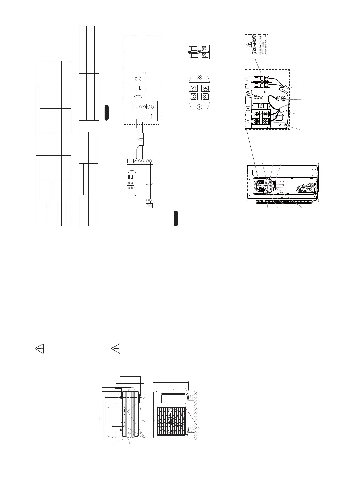
4-3. Wiring System Diagrams
R2
R1
U2
U1
L
N
B
A
C
L
N
L
N
U2
U1
N
L
SG
SG
2
1
2
1
D
7(4
",+
Remote
controller
Power supply
6^(Z
Ground
Ground
Indoor unit
(SG : Shows the ground for the shielded cable.)
Outdoor unit (single-phase)
INV unit
Power supply
6^(Z
NOTE
3EETHESECTIONh2ECOMMENDED7IRE,ENGTHAND7IRE
$IAMETERFOR0OWER3UPPLY3YSTEMvFORTHEEXPLANATIONOFh!vh"v
h#vANDh$vINTHEABOVEDIAGRAMS
(2) The basic connection diagram of the indoor unit shows the
terminal board, so the terminal boards in your equipment may
differ from the diagram.
(3) Refrigerant Circuit (R.C.) address should be set before turning the
power on.
(4) Regarding R.C. address setting, refer to the installation
instructions supplied with the remote controller unit (Optional).
Auto address setting can be executed by remote controller
automatically. Refer to the installation instructions supplied with
the remote controller unit (optional).
■
Wiring sample
Earth
Earth
Use this screw when connecting to
ground for the Inter-unit control wiring
Power supply
Power supply
Cord clamp
(Field supply)
Cord clamp A
#ORDCLAMP"
Cord clamp C
Inter-unit control wiring
Inter-unit control wiring
Throw away above label
after wiring.
L N U1 U2
Power supply Inter-unit control wiring
2P terminal board 2P terminal board
4-2. Recommended Wire Length and Wire Diameter for Power Supply System
Control wiring
(C) Inter-unit (between outdoor
and indoor units) control wiring
(D) Remote control wiring
0.75 mm
2
(AWG #18)
Use shielded wiring*
1
0.75 mm
2
(AWG #18)
Use shielded wiring
Max. 1,000 m Max. 500 m
NOTE
*1
With ring-type wire terminal.
Outdoor unit
(A) Power supply Time delay
fuse or circuit
capacity
(A) Power supply Time delay
fuse or circuit
capacity
Wire size Max. length Wire size Max. length
U-36PE2E5A 2.5 mm² 22 m 20 A 4 mm² 35 m 20 A
U-50PE2E5A 2.5 mm² 22 m 20 A 4 mm² 35 m 20 A
U-60PE2E5A 2.5 mm² 17 m 25 A 4 mm² 27 m 25 A
U-60PEY2E5 2.5 mm² 17 m 25 A 4 mm² 27 m 25 A
U-71PEY2E5 2.5 mm² 17 m 25 A 4 mm² 27 m 25 A
Indoor unit
Type
(B) Power supply
Time delay fuse or
circuit capacity
2.5 mm
2
+ Max. 150 m 10-16 A
U2, Y2, T2, F1, N1 Max. 130 m 10-16 A
10
00_2WAY_All_282008.indb 1000_2WAY_All_282008.indb 10 2016/12/1 9:55:132016/12/1 9:55:13
 Loading...