Do you have a question about the Panasonic CS-CZ9SKE and is the answer not in the manual?
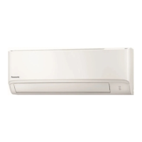
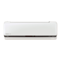
Identifies the location and function of controls and components on the indoor unit, including air filters and louvers.
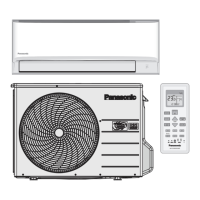
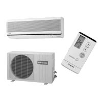
Identifies the location of air inlets and outlets on the outdoor unit.
Identifies buttons and display elements on the remote control transmitter.
Provides dimensional drawings and measurements for the indoor unit and remote control.
Details the dimensions and diagrams for the outdoor unit, including views and measurements.
Illustrates the wiring connections for the indoor unit, including components and terminal board.
Details the wiring diagram for the outdoor unit, showing connections to compressor, fan, and sensors.
Presents the electronic circuit diagram for the indoor unit, including controller and sensors.
Shows the electronic circuit diagram for the outdoor unit, detailing components and sensor characteristics.
Illustrates the main printed circuit board and indicator/receiver board for the indoor unit.
Shows the main printed circuit board for the outdoor unit, detailing component locations.
Guidelines for selecting optimal installation locations for indoor and outdoor units.
Detailed procedures for installing the indoor unit, including mounting and wiring.
Comprehensive steps for installing the outdoor unit, including piping, wiring, and evacuation.
Provides background information on R32 refrigerant, its properties, and environmental impact.
Lists and describes tools required for R32 refrigerant piping installation and servicing.
Outlines the procedural flow for new installation, relocation, and refrigerant cycle repairs.
Covers air purging, leak testing, refrigerant recovery, relocation, and replacement procedures.
Details preparation, materials, and techniques for brazing refrigerant cycles.
Provides methods for diagnosing issues by analyzing refrigerant cycle behavior.
Explains inverter control, internal temperature settings, and basic operation modes like cooling, soft dry, and heating.
Covers manual and automatic fan speed settings, rotation speeds, and feedback control mechanisms.
Describes how vertical and horizontal airflow directions are controlled, both automatically and manually.
Explains how to set and use ON and OFF timers for unit operation.
Explains how to activate and control quiet operation for cooling and heating modes.
Covers restart control, total running current limits, and IPM prevention controls.
Explains low pressure detection and the resulting protection actions for gas leakage.
Details protection controls specific to cooling and soft dry operations like freeze and dew prevention.
Covers protection controls specific to heating operations like intake air temperature and overload protection.
Explains how to use the Auto OFF/ON button for auto operation, test run, and remote control mode switching.
Describes using buttons like SET for transmission code storage and temperature range limits.
Basic diagnostics for refrigeration cycle issues, including temperature and pressure checks.
Table showing how various conditions affect pressure and electric current during operation.
How to access and interpret error codes displayed in a three-digit alphanumeric format.
A comprehensive table listing error codes, their causes, and check locations.
Troubleshooting steps for specific error codes like H11, H12, H14, H15, and others.
Procedures for removing front grille, electronic controller, and fan motor from the indoor unit.
Step-by-step instructions for removing the electronic controller from the outdoor unit, with safety precautions.
Provides cooling performance data (capacity, SHC, IP) for different indoor/outdoor conditions.
Presents heating performance data (capacity, IP) for various outdoor temperatures.
Graphs showing outlet air temp, current, and low pressure vs. outdoor air temp.
Graphs showing outlet air temp, current, and high pressure vs. outdoor air temp for heating.
Shows graphs for adjusting cooling and heating capacity based on piping length.
An exploded view of the indoor unit with numbered parts for identification and replacement.
An exploded view of the outdoor unit with numbered parts, useful for disassembly and replacement.
| Brand | Panasonic |
|---|---|
| Model | CS-CZ9SKE |
| Category | Air Conditioner |
| Language | English |