Do you have a question about the Panasonic DMP-BD60 and is the answer not in the manual?
Instructions for manually selecting Blu-ray regions using the player's remote control while in standby mode.
Important warnings about voiding warranty, required tools, and preparation steps before fitting the mod. chip.
Procedure for removing the player's top cover and identifying areas on the main board for mod. chip connections.
Details on connecting mod. chip pin #1 to specific solder pads on the player's main board.
Instructions for connecting mod. chip pins #2, #3, #4, and #8 to a small 8-pin chip on the main board.
Steps to remove the front panel and connect mod. chip pin #5 to the front panel PCB.
Connecting pin #5 to the front panel PCB and ensuring correct re-fitting of the front panel clips.
Explains connecting mod. chip pins using wires or the 'piggy-back' method on the 8-pin chip.
Guide to bending, positioning, and soldering mod. chip pins #8, #2, #3, and #4 for the piggy-back connection.
Visual examples of the completed mod. chip installation, including wire placement for pins #1 and #5.
Guidance on using wires to connect all six mod. chip pins as an alternative to the piggy-back method.
| Type | Blu-ray Player |
|---|---|
| BD-Live | Yes |
| Output Resolution | 1080p |
| Audio Decoding | Dolby Digital, Dolby Digital Plus, DTS, DTS-HD |
| Video Upscaling | Yes |
| HDMI Output | Yes |
| Ethernet Port | Yes |
| USB Port | Yes |
| Component Video Output | Yes |
| Composite Video Output | Yes |
| Dolby Digital Decoding | Yes |
| Dolby Digital Plus Decoding | Yes |
| DTS Decoding | Yes |
| DTS-HD Decoding | Yes |
| Progressive Scan | Yes |
| Remote Control | Yes |
| Blu-ray Profile | 2.0 |
| Supported Discs | BD, DVD, CD |
| Digital Audio Output | Optical |
| Analog Audio Output | Yes |
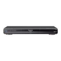
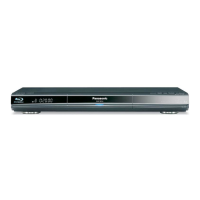
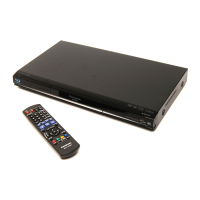
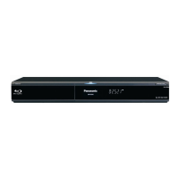

 Loading...