11.1. SERVICE POSITIONS
11 MEASUREMENTS AND ADJUSTMENTS
Note:
For description of the disassembling procedure, see the section ASSEMBLING AND DISASSEMBLING
(DISASSEMBLY FLOW CHART).
11.1.1. CHECKING AND REPAIRING OF POWER P.C.B.
1. Top Case
· Remove 2 Screws (A) on side
· Remove 3 rear Screws (B) on rear
· Remove Top Case
2. Power P.C.B.
· Remove 1 Screw for AC Inlet fixing
· Remove 3 Screws fixing Power P.C.B.
· Remove 1 Connector to Main P.C.B.
· Remove 1 Connector to Fan P.C.B.
· Lift up Power P.C.B. sideways out of the Guide Pins.
· Connect Extension Cable:
− between Main P.C.B. and Power P.C.B. with RFKZ0216
− between Fan Motor and Power P.C.B. with RFKZ0168
· Put Power P.C.B. on Insulation Board so that it’s solder side faces top
Caution 1
Red wire in the extension cable should be connected to pin 1
Caution 2
Orginal screws should be used
37
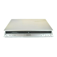
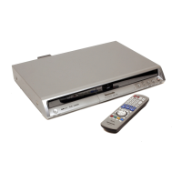
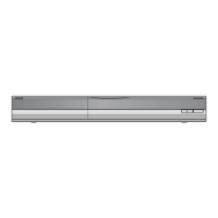
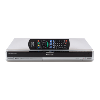
DMR-EX75EG / DMR-EX75EC / DMR-EX75EB / DMR-EX85EG / DMR-EX85EB
 Loading...