FUNCTIONAL DESCRIPTION
6
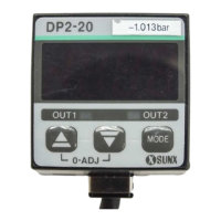
DP2-20
-101.3kPa
OUT2OUT1
MODE
0-ADJ
ձ
ղ
ճ
ն
մ
յ
࣭
࣭
࣭
Pressi n g t he key ch anges t h e sel ect ed
mode to sensing mode, Set Value 1 (P1)
set mode and Set Value 2 (P2) set mode.
In the sensing mode, if the key is
pressed co n t i nuou sl y f o r ab o ut 3 sec.,
key-protect can be set/released.
In the sensing mode, if the mode selection
key is pressed while pressing t he increment
key , the initial setting mode is obtained.
Lights up when Comparati ve Out put 1 is ON.
ղ
Comparat ive Out p ut 1
operation indicator
(Orange)
Comparat ive Out p ut 2
operation indicator
(Green)
Di sp l ays measured p r essure, set t i ngs,
erro r messag es and key-p rot ect st at u s.
Description Function
ձ
3
1
㸭
2
digit LED
display (Red)
Lights up when Comparati ve Out put 2 is ON.
ճ
ն
In t he sensing mode, if bot h t he keys are pressed
simultaneously, zero-point adjustment is done.
࣭
࣭
࣭
In the initial setting mode, pressing
the key changes the settable digit.
In t he Set Value 1, 2 modes, press-
ing the key changes the set value
t o t h e high pressu re side in case o f
posit i ve p r essu re t ype sensor and
to the high vacuum side in case of
vacu um pressur e t yp e senso r.
In the sensing mode, if the key is press-
ed continuously for 4 sec. or more, the
display show s p eak ho l d val ue.
մ
Increment key
࣭
࣭
࣭
In the initial setting mode, pressing
the key changes the set conditions.
In t he Set Value 1, 2 modes, press-
ing the key changes the set value
t o t h e l ow pressu re si d e i n case of
posit i ve p r essu re t ype sensor and
to the low vacuum side in case of
vacu um pressur e t yp e senso r.
In the sensing mode, if the key is press-
ed continuously for 4 sec. or more, the
display show s b o t t om ho l d val ue.
յ
Decrement key
Mode selection key
MODE
ERROR MESSAGES
7
ە
When an error occurs, take the following corrective action.
3RVLWLYH
SUHVVXUH
W\SH
3RVLWLYH
SUHVVXUH
W\SH
9DFXXP
SUHVVXUH
W\SH
9DFXXP
SUHVVXUH
W\SH
Applied pressure exceeds
the upper limit of display-
able pressure range.
Applied pressure exceeds
the lower limit of displaya-
ble pressure range.
Applied pressure exceeds
the lower limit of displaya-
ble pressure range.
Applied pressure exceeds
the upper limit of display-
able pressure range.
Applied pressure at the pressure
port should be brought to atmos-
pheric pressure and zero-point
adj ust ment should be done agai n.
Pressure is being ap-
plied during zero-point
adj ust ment .
Switch off the power
supply and check the
load.
Corrective action
Overcurrent due t o
short-circuit.
Error message
Cau se
Applied pressure should
be brought within the
rated pressure range.
Analog bar display for positive pressure type sensor
Atm. pressure condition
High pressure condition
Atm. pressure condition
High vacuum condition
Analog bar display for vacuum pressure type sensor
ANALOG BAR DISPLAY
8
ە
ە
PressurechangesaredisplayedinananalogfashionbyusingLEDbars.
Hence,anysuddenchangesinpressurecanbedetectedataglance.
The analog bar display shows the measured pressure,
irrespectiveofthepressureunit,instepsof10%F.S.approx.
Pleaserefer to 'SETTING ĭInitialsetting' for the
proceduretochangetoanalogbardisplay.
11
DP2-21
100kPa
OUT2OUT1
MODE
0-ADJ
DP2-21
100kPa
OUT2OUT1
MODE
0-ADJ
DP2-21
100kPa
OUT2OUT1
MODE
0-ADJ
DP2-20
-101.3kPa
OUT2OUT1
MODE
0-ADJ
DP2-20
-101.3kPa
OUT2OUT1
MODE
0-ADJ
DP2-20
-101.3kPa
OUT2OUT1
MODE
0-ADJ
MOUNTING OF STANDARD
TYPE SENSOR
4
ە A sensor mounting bracket MS-DPX and MS-DPX-4
(optional) may be used.
When mounting the sensor with the sensor mounting
bracket, etc., the tightening torque should be 1.2N㺃m
or less.
Note: In case mounting brackets or screws other than the
sensor mounting bracket shown in the figure above
are used, the lengt h of t he screws inserted int o the
pressu r e p ort at t ach men t shoul d b e 5mm or less. If
the length of the screws is longer than 5mm, the
sensor may be damaged.
<MS-DPX>
Sensor mounting bracket
MS-DPX (optional)
M4 (length 6mm) pan head screw
(attached with MS-DPX)
Sp r i n g w ash er
(attached with MS-DPX)
<MS-DPX-4>
Sensor mounting
bracket
MS-DPX-4 (opt ional)
M4 (length 6mm) pan head screw
(attached with MS-DPX-4)
Sp r i n g w ash er
(attached with MS-DPX-4)
ە
Panel mounting bracket MS-DPX-2 (opt ional) and a front
protection cover DPX-04 (optional) are also avail able.
DP2-20
–
101.3kPa
OUT2
OUT1
MODE
0-ADJ
Panel mounting bracket
MS-DPX-2 (opt ional)
(Suitable for 1 to 3.2mm thick panel)
DP2-20
-101.3kPa
OUT2
OUT1
MODE
0-ADJ
Front protection cover
DPX-04 (optional)
I/O CIRCUIT DIAGRAM
5
ە NPN output type
Not e:
The analog volt age out put is not incorporated with a
short-circuit protection circuit. Do not directly connect
a power supply or a capacitive load. When using the
analog voltage output, take care to connect external
equipment of proper input impedance.
Also, when a cable extension is used, volt age drop
due to cable resistance should be taken into account.
Tr2
Tr1
1kȐ
100mA max.
100mA max.
Users’ circuitInternal circuit
(Blue) 0V
(White) Comparative Output 2
(Black) Comparat ive Out put 1
(Gray) Analog
volt age out put
(Brown) +V
Co l o r co de
Load
Load
Z
D2
Z
D3
Z
D1
D
Se n so r c i r c u i t
(Not e)
12 to 24V
DC
10
15
ࠉ %
Symbols... D: Reverse supply polarity protection diode
Z
D1, ZD2, ZD3: Surge absorption zener diode
T
r1, Tr2: NPN output t ransistor
Symbols... D: Reverse supply polarity protection diode
Z
D1, ZD2, ZD3: Surge absorption zener diode
T
r1, Tr2: PNP out p u t t ran si st o r
ە PNP output t yp e
Not e:
The analog volt age out put is not incorporated with a
short-circuit protection circuit. Do not directly connect
a power supply or a capacitive load. When using the
analog voltage output, take care to connect external
equipment of proper input impedance.
Also, when a cable extension is used, volt age drop
due to cable resistance should be taken into account.
Users’ circuitInternal circuit
Co l o r co de
100mA max.
100mA max.
ZD1
ZD2
ZD3
Tr1
Load
Load
(Brown) +V
(White) Comparative Output 2
(Black) Comparat ive Out put 1
(Gray)Analog
volt age out put (Not e)
(Blue) 0V
Tr2
D
Se n so r c i r c u i t
1kȐ
12 to 24V
DC
10
15
ࠉ %
PRESSURE UNITS
10
ە
ە
The pressure unit can be selected as per cust omer's requirement.
In case o f p osi t i v e p ressu re t ype, t h e pressure un i t can b e
changed from International System of Units (SI) 'kPa' or 'MPa'
to 'kgf/cm
2
', 'bar' or 'psi'. In case of vacuum pressure type, the
pressu r e u n it can b e ch an g ed from Int ernat i onal Syst em of
Units (SI) 'kPa' to 'kgf/cm
2
', 'bar', 'psi', 'mmHg' or 'inHg'.
࣭
࣭
When t he pressure unit is changed, the set values
and the measured value are automat ically convert ed.
Please refer to ' SETTING ĭ Initial setting' for
the procedure t o change the pressure unit.
11
Not e:
'MPa' in case of DP2-22ڧ, DP2-42ڧ and DP2-62ڧ.
inHg
kPa (Not e)
kgf/cm
2
mmHg psi bar
: Posit i ve p r essu re t yp e: Vacuum pressure type
Int ernational System
of Units (SI)
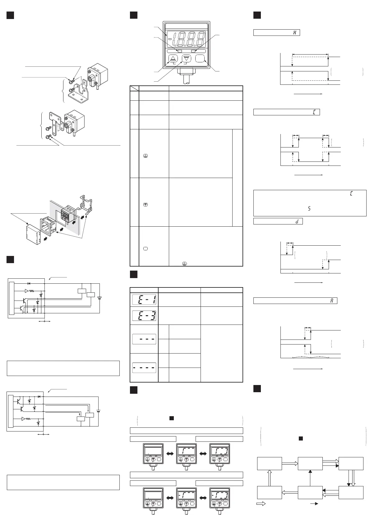
OUTPUT MODES & THEIR
CHARACTERISTICS
9
ە The common hysteresis of the comparative output s
can be set, as desired, with the set values.
Hysteresis mode ( )
Comparat ive
Out put 1
Comparat ive
Out put 2
Hysteresis:
1 digit or more
2 digits or more
when using psi unit
ON
OFF
ON
OFF
0
Set Value 1 (P1) Set Value 2 (P2)
Hi g h p ressu r e
(Positive pressure type)
High vacuum
(Vacuum pressure type)
Hysteresis
ە
The comparative out puts can be turned ON or OFF by a pressure
which is within the pressure range set by Set Value 1 and Set Value 2.
Window comparator mode ( )
When operating in window comparator mode ( ) Set
Value 1 (P1) and Set Value 2 (P2) should be set with a
difference of 3 digits or more. However, when the
pressu r e u n it is set t o ' p si ' ( ), t he d if f er ence should b e 6
digits or more.
Hysteresis: 1 digit
2 digit s when using
psi unit
Hi g h p ressu r e
(Positive pressure type)
High vacuum
(Vacuum pressure type)
Comparat ive
Out put 1
Comparat ive
Out put 2
ON
OFF
ON
OFF
0
Set Value 1 (P1)
Set Value 2 (P2)
Hysteresis Hysteresis
ە
Using actual objects, if the pressure values for OK ob-
jects and NG objects are input, then the sensor is auto-
matically set to the optimum pressure value (mid-value).
Automatic sensitivity setting mode ( )
Comparat ive
Out put 1
Comparat ive
Out put 2
ON
OFF
ON
OFF
0
Set Value 1 (P1) Set Value 2 (P2)
Hi g h p ressu r e
(Positive pressure type)
High vacuum
(Vacuum pressure type)
Set Value 3 (P3)
Hysteresis
Hysteresis: 1 digit
2 digit s when using
psi unit
ە
The outputs can be put to different use such as detection of
different kinds of objects, control function, alarm function etc.
Dual output mode ( )
Hi g h p ressu r e
(Positive pressure type)
High vacuum
(Vacuum pressure type)
Comparat ive
Out put 1
Comparat ive
Out put 2
ON
OFF
ON
OFF
0
Set Value 1 (P1) Set Value 2 (P2)
Hysteresis
Hysteresis: 1 digit
2 digit s when using
psi unit
 Loading...