Fig.2-A
Fig.2-C
Fig.2-B
Fig.2-D
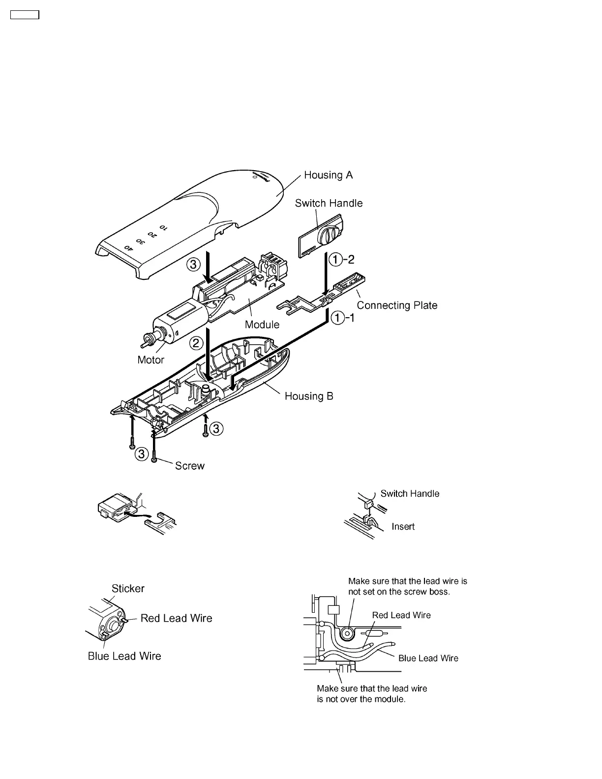
4 ASSEMBLY INSTRUCTIONS
1. Place the connecting plate and the switch handle onto the housing B with OFF position.
NOTE 1: Do not touch the contact metal plate to prevent its deformation. (See Fig.2-A.)
NOTE 2: Set the switch handle into the slit of connecting plate firmly. (See Fig.2-B.)
2. Set the module and the motor placing the sticker on top. (See Fig.2-C.)
Press fit the lead wires neatly. (See Fig.2-D.)
NOTE: Make sure if the motor rotates when switching ON.
3. Close the housing A and B, and tighten three screws.
4
ER507-E2