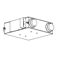
This document provides installation and operating instructions for the Panasonic Energy Recovery Ventilator (ERV) models FV-10VEC2, FV-10VEC2H, FV-10VE2, and FV-10VE2H.
Function Description
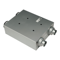
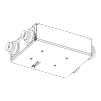
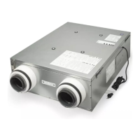
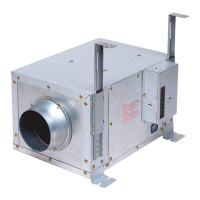
The Panasonic ERV is designed to transfer heat and moisture between stale exhaust air (EA) and fresh outside air (OA). Unlike Heat Recovery Ventilators (HRVs), ERVs can also recover energy from humidity. This process helps maintain a fresh indoor environment by pre-cooling and reducing humidity in incoming hot air, or by transferring heat and moisture into incoming cold air, even when the heating or cooling system is not operating. This ensures a comfortable indoor climate while minimizing energy loss. The unit is intended for general ventilating use only and should not be used to exhaust hazardous or explosive materials and vapors.
Important Technical Specifications
General:
- Power Supply: AC 120 V, 60 Hz
- Wall Switch/Boost Switch Capacity: Must be more than 120 V~3 A.
- Installation Environment: Must be installed in a mechanical room, basement, or other conditioned space where air temperature is above 50 °F (10 °C) to avoid condensation. Not to be installed in high humidity spaces like bathrooms, kitchens, or laundry rooms. Canada only: Not to be installed in a ceiling thermally insulated to a value greater than R40.
- Duct Connections: OA and EA ducts must be connected directly to the outside. A minimum separation of 40 inches (1 m) is recommended between direct connections to the furnace. The exhaust air connection should be upstream of the supply air connection to prevent exhausting fresh air. Outdoor hoods should be located at least 10 ft (3 m) apart. The intake side duct must be connected to the outside and at least 6 ft (1.8 m) away from the exhaust of appliances such as furnaces, dryers, or fuel-burning appliances.
- Duct Size: Compatible with 4" or 6" adapters.
- Duct Type: Rigid galvanized ducting is recommended, with a 6-inch section of flexible duct to connect rigid ducts to avoid vibration transmission.
- Airflow Balancing: The ERV unit must be balanced, and airflow must be confirmed on site using the balancing procedures outlined in the manual.
- HVAC/AHU Connection: It is mandatory that the HVAC/AHU signal cord be connected for proper operation and balancing.
Performance (FV-10VEC2/FV-10VEC2H):
- Air Direction: Exhaust & Supply
- Voltage: 120 V
- Frequency: 60 Hz
- Duct Size: 4"/6"
- Static Pressure: 0.1"WG, 0.4"WG
- Net Air Flow (CFM): 100 (Exhaust), 100 (Supply)
- Power Consumption (W): 81 (0.1"WG), 90 (0.4"WG)
- Weight: 50 lb (22.4 kg)
Performance (FV-10VE2/FV-10VE2H):
- Air Direction: Exhaust & Supply
- Voltage: 120 V
- Frequency: 60 Hz
- Duct Size: 4"/6"
- Static Pressure: 0.1"WG, 0.4"WG
- Net Air Flow (CFM): 100 (Exhaust), 100 (Supply)
- Power Consumption (W): 81 (0.1"WG), 90 (0.4"WG)
- Weight: 48 lb (21.6 kg)
Energy Performance (FV-10VEC2/FV-10VEC2H):
- Heating (32 °F/0 °C):
- Net Air Flow: 53 CFM (25 L/s) - Power: 29 W - Sensible Recovery Efficiency: 80% - Adjusted Sensible Recovery Efficiency: 83% - Net Moisture Transfer: 0.78
- Net Air Flow: 66 CFM (31 L/s) - Power: 39 W - Sensible Recovery Efficiency: 77% - Adjusted Sensible Recovery Efficiency: 81% - Net Moisture Transfer: 0.74
- Net Air Flow: 85 CFM (40 L/s) - Power: 68 W - Sensible Recovery Efficiency: 73% - Adjusted Sensible Recovery Efficiency: 77% - Net Moisture Transfer: 0.71
- Heating (-13 °F/-25 °C):
- Net Air Flow: 57 CFM (27 L/s) - Power: 77 W - Sensible Recovery Efficiency: 65% - Adjusted Sensible Recovery Efficiency: 67% - Net Moisture Transfer: 0.71
- Net Air Flow: 64 CFM (30 L/s) - Power: 100 W - Sensible Recovery Efficiency: 56% - Adjusted Sensible Recovery Efficiency: 60% - Net Moisture Transfer: 0.58
- Cooling (95 °F/35 °C):
- Net Air Flow: 49 CFM (23 L/s) - Power: 32 W - Total Recovery Efficiency: 60%
- Net Air Flow: 66 CFM (31 L/s) - Power: 42 W - Total Recovery Efficiency: 55%
Energy Performance (FV-10VE2/FV-10VE2H):
- Heating (32 °F/0 °C):
- Net Air Flow: 53 CFM (25 L/s) - Power: 29 W - Sensible Recovery Efficiency: 80% - Adjusted Sensible Recovery Efficiency: 83% - Net Moisture Transfer: 0.78
- Net Air Flow: 66 CFM (31 L/s) - Power: 39 W - Sensible Recovery Efficiency: 77% - Adjusted Sensible Recovery Efficiency: 81% - Net Moisture Transfer: 0.74
- Net Air Flow: 85 CFM (40 L/s) - Power: 68 W - Sensible Recovery Efficiency: 73% - Adjusted Sensible Recovery Efficiency: 77% - Net Moisture Transfer: 0.71
- Cooling (95 °F/35 °C):
- Net Air Flow: 49 CFM (23 L/s) - Power: 32 W - Total Recovery Efficiency: 60%
- Net Air Flow: 66 CFM (31 L/s) - Power: 42 W - Total Recovery Efficiency: 55%
Usage Features
Installation:
- Wall Mount (Method I): The unit can be mounted on wall studs. Wall brackets are attached with the flanged edge facing outward and the non-flanged edge facing upward. Mounting holes are chosen based on stud distance. Hanger I and L plates are then installed, followed by hanging the ERV onto the wall bracket.
- Chain Mount (Method II): For 24-inch joists, the unit can be chain-mounted. Chains (not supplied, must support 66 lbs/30 kg or more) are attached to Hanger II plates, which are then installed on the joists. The unit must be horizontal after installation.
- Duct Installation Methods:
- Method I (Simplified Ducted - Return Method): Draws return air from the furnace's return air duct and supplies outside air downstream into the return duct. Requires HVAC/AHU signal cord connection.
- Method II (Partially Dedicated Ducted): Draws return air from specific points in the home (e.g., bathrooms, kitchens) and supplies outside air into the furnace's return air duct. The furnace blower should run with the ERV. Requires HVAC/AHU signal cord connection.
- Method III (Fully Dedicated Ducted): Draws return air from specific points and supplies outside air to specific locations (e.g., bedrooms, living rooms) without connecting to an air furnace.
- Ducting Requirements: All duct attachments require 2-3 ft (610 mm) straight runs before elbows. Insulated ducts are used for OA and EA adapters, while rigid galvanized ducts are used for SA and RA adapters. Mastic or approved foil tape should be used to seal connections.
Operation (Control Panel):
- Main Switch: Powers the ERV on or off. Pushing it completely to the on/off position activates or deactivates the unit. The unit consumes electricity unless the main switch is off.
- ASHRAE Time Knob: Adjusts the operation state in cycles (e.g., "10" for 10 minutes ON, 50 minutes OFF, 10 minutes ON...). Factory default is 60 Min/H.
- SA Knob: Sets the supply air volume (CFM). Factory default is 100 CFM.
- EA Knob: Sets the exhaust air volume (CFM). Factory default is 100 CFM.
- Air Volume Restriction: When outdoor temperature is ≤14 °F (-10 °C), the SA air volume is limited to "EA air volume + 20 CFM" to protect the energy recovery core.
- Operation Modes:
- Heat Exchange Mode: EA damper open, center damper closed.
- Circulation Mode (for defrost): EA damper closed, center damper open. This mode is activated automatically for defrosting, especially in colder temperatures.
- ASHRAE Timer/Boost Switch: When the ASHRAE timer is set to 60 min/h or the boost switch is on, the ERV enforces specific settings (ASHRAE: 60 min/h, SA: 100 CFM, EA: 100 CFM). When the boost switch is off, it reverts to customer settings.
- Continuous Operation: It is recommended to operate the product for 24 hours to prevent freezing.
Maintenance Features
Routine Maintenance (Every 2-3 months):
- Filter Cleaning/Replacement: Clogged filters can reduce airflow and cause condensation.
- Open the frame cover by unlocking the latches.
- Clean the OA filter, RA filter, and energy recovery core.
- Reinstall the filters, ensuring the arrow on the OA filter indicates the correct airflow direction.
- Reinstall and close the frame cover, then reset the lock plate.
- OA Filter Replacement: It is suggested to replace the OA filter every 6 months with Panasonic Model FV-FL0810VE1 or FV-FL1310VE1.
- Filter Indicator and Reset: The filter indicator lights up when the accumulated run time reaches 90 days, accompanied by a buzzing sound every hour for 10 seconds. Pressing the filter reset button for 3 seconds (until a long beep) turns off the buzzer. Pressing it again (until two quick beeps) turns the buzzer indication back on. After filter maintenance, press the reset button to clear the accumulated run time and turn off the indicator/buzzer.
- Condensed Water Discharge: After running in low temperatures, remove the 4 plugs to discharge condensed water.
Safety Precautions during Maintenance:
- Always disconnect power by switching off the main switch first, then unplug the unit before working on it.
- Wear gloves to avoid pinching fingers.
- Be cautious of dust, condensation water, or falling parts when opening the frame cover.
- Never use petrol, benzene, thinner, or other harsh chemicals to clean the ERV.
- Do not allow water to enter the ERV.
- Do not immerse resin parts in water over 60 °C.
Troubleshooting:
The manual provides a troubleshooting guide for common issues such as the ERV not working, HVAC/AHU not working, buzzer sound, and incorrect air volume based on settings. It includes display indicators (running indicator - green, filter indicator - red) and corresponding actions, such as checking power connections, frame cover, main switch, or contacting the dealer for motor, damper, sensor, or PCB errors. It also explains automatic operation adjustments based on outdoor temperature (e.g., defrosting, air volume restriction).
Product Service:
The unit should only be serviced by qualified technicians. For service or parts, contact the Panasonic Call Center at 1-866-292-7299 (USA) or 1-800-669-5165 (Canada).