EasyManua.ls Logo

Panasonic HG-C Series User Manual

Panasonic HG-C Series
4 pages
To Next Page IconTo Next Page
Page #1 background imageLoading...
Page #1 background image
Easy user guide
Please follow the procedure from step 1 to 5.
Adjust the height of the sensor.
1
Mounting
HG-C measurement sensor
Example: HG-C1050-P
Adjusted height 50mm
Product No.
Measurement
center distance and
measuring range
Analog output Cable length
Voltage
output
Current
output
HG-C1030-P 30±5mm 0 to +5V 4 to 20mA 2m
HG-C1030 30 ±5mm 0 to +5V 4 to 20mA 2m
HG-C1050-P 50 ±15mm 0 to +5V 4 to 20mA 2m
HG-C1050 50 ±15mm 0 to +5V 4 to 20mA 2m
HG-C1100-P 100 ±35mm 0 to +5V 4 to 20mA 2m
HG-C1100 100 ±35mm 0 to +5V 4 to 20mA 2m
HG-C1200-P 200 ±80mm 0 to +5V 4 to 20mA 2m
HG-C1200 200 ±80mm 0 to +5V 4 to 20mA 2m
HG-C1400-P 400 ±200mm 0 to +5V 4 to 20mA 2m
HG-C1400 400 ±200mm 0 to +5V 4 to 20mA 2m
M3 screws
(not included)
18mm
37mm
Mounting hole dimensions

Other manuals for Panasonic HG-C Series

Question and Answer IconNeed help?

Do you have a question about the Panasonic HG-C Series and is the answer not in the manual?

Panasonic HG-C Series Specifications

General IconGeneral
Linearity±0.1% F.S.
SeriesHG-C
Output ConfigurationNPN or PNP
Power Supply Voltage12 to 24 V DC ±10%
Protection RatingIP67
ConnectionConnector

Summary

Mounting

Wiring

Sensor Components and Connections

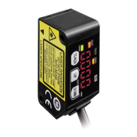
Details sensor parts, indicators, and wiring connections for power supply.

Measuring (analog)

Zero Point Setting

Procedure for calibrating the zero point before measurement.

Measurement Setup

Illustrates correct sensor placement and measurement.

Limit Teaching (Digital)

Related product manuals