CAUTIONS
2
٨
٨
٨
٨
٨
٨
٨
٨
٨
٨
٨
٨
٨
٨
This product has been developed / produced
for industrial use only.
Make sure that the power is off while wiring.
Take care that wrong wiring will damage the
sensor.
Verify that the supply voltage variation is
within the rating.
If power is supplied from a commercial
switching regulator, ensure that the frame
ground (F.G.) terminal of the power supply is
connected to an actual ground.
In case noise generating equipment (switch-
ing regulator, inverter motor, etc.) is used in
the vicinity of this product, connect the frame
ground (F.G.) terminal of the equipment to an
actual ground.
Do not run the wires together with high-volt-
age lines or power lines or put them in the
same raceway. This can cause malfunction
due to induction.
Do not use during the initial transient time
(20ms) after the power supply is switched on.
Take care that the sensor is not directly exposed
to fluorescent lamp from a rapid-starter lamp, a
high frequency lighting device or sunlight etc., as
it may affect the sensing performance.
Extension up to total 100m, or less, is possi-
ble with 0.3mm
2
, or more, cable. However, in
order to reduce noise, make the wiring as
short as possible.
Make sure that stress by forcible bend or pulling
is not applied directly to the sensor cable joint.
This sensor is suitable for indoor use only.
Do not use this sensor in places having exces-
sive vapor, dust, etc., or where it may come in
direct contact with water, or corrosive gas.
Take care that the sensor does not come in
contact with water, oil, grease, organic sol-
vents, such as, thinner etc., or strong acid,
and alkaline.
MOUNTING
3
٨
The tightening torque should be 0.39N㨯m or
less.
EX-M2
M3 (length 16mm)
screw with washers
Sensor mounting bracket
MS-EX-1 (Accessory)
٨ The tightening torque must not exceed the
values given below.
EX-M2E: 0.58N㨯m
EX-D200E: 0.39N㨯m
EX-M2E, EX-D200E
M3 (length 16mm)
screw with washers
Sensor mounting bracket
MS-EX-1E (Accessory)
٨
٨
Never use this product as a sensing
device for personnel protection.
In case of using sensing devices for
personnel protection, use products
which meet laws and standards,
such as OSHA, ANSI or IEC etc., for
personnel protection applicable in
each region or country.
WARNING
SPECIFICATIONS
1
㧙
㧙
15% or less of operation distanceHysteresis
Material
MS-EX-1E (Sensor mounting bracket): 1 set
Adjusting screwdriver: 1 pc.
Adjuster cap: 1 pc.
30mA or less
12 to 24V DCr10% Ripple P-P 10% or lessSupply voltage
Emitter: 20mA or less, Receiver: 20mA or lessCurrent consumption
0.04mm or less
㧙
0.1mm or less
Repeatability
(perpendicular to sensing axis)
0.14mm
2
4-core (thru-beam type sensor emitter: 2-core) oil, heat and cold resistant cabtyre cable, 3m longCable
Enclosure: Black PBT (Glass fiber reinforced), Lens: Polycarbonate
Infrared LED (modulated)Emitting element
IP65 (IEC)Protection
-10 to +60 (No dew condensation or icing allowed), Storage: -30 to +70Ambient temperature
35 to 85% RH, Storage: 35 to 85% RHAmbient humidity
Continuously variable adjusterSensitivity adjuster
Red LED (lights up when the output is ON), thru-beam type sensor: located on the receiverOperation indicator
1ms or lessResponse time
Light-ON or Dark-ON operation can be selected by changing the connection of the control input wire
Incorporated
Output
Output operation
Short-circuit protection
NPN open-collector transistor
Maximum sink current: 100mA
Applied voltage: 30V DC or less (between output and 0V)
Residual voltage: 1V or less (at 100mA sink current)
0.4V or less (at 16mA sink current)
MS-EX-1E (Sensor mounting bracket): 2 sets
MS-EX-1 (Sensor mounting bracket): 2 sets
65g approx.
Emitter: 60g approx., Receiver: 60g approx. Emitter: 60g approx., Receiver: 65g approx.
Weight
Accessories
Side sensing
2m
200mm (Note 2)
Sensing range
EX-M2 EX-D200EEX-M2E
Model No. (Note 1)
Item
Top sensingSide sensing
Thru-beam Diffuse reflective
Type
Ǿ7mm or more opaque object (Note 3)
Opaque, translucent or transparent object
Sensing object
Notes: 1)
2)
3)
The model No. with suffix 'P' shown on the label affixed to the thru-beam type sensor is the emitter, 'D' shown on the label is the receiver.
Thru-beam type sensor emitter: EX-M2غP, Thru-beam type sensor receiver: EX-M2غD
The sensing range of the diffuse reflective type sensor is specified for white non-glossy paper (200 200mm) as the object.
If the slit mask (optional) is fitted, an object of EX-M2E: 0.53mm, EX-M2: 0.52mm can be detected.
I/O CIRCUIT DIAGRAMS
4
*1:
Selecting output operation be connecting
control input wire (pink)
D
T
r
ZD
㧗
㧙
12㨪24V DC
r10%
Sensor circuit
Internal circuit Users' circuit
Load
(Black)
Output (Note)
(Blue) 0V
(Pink) Control input
(Note)
(Brown) +V
100mA max.
*1
Connection
Connected to 0V
Light-ON Light-ON Dark-ON
Connected to +V
Dark-ON
㧙㧙
Open Dark-ON Light-ON
Model No.
EX-M2E EX-M2 EX-D200E
Note: The thru-beam type sensor emitter does not incorporate.
Symbols...
D
ZD
Tr
: Reverse supply polarity protection diode
: Surge absorption zener diode
: NPN output transistor
Color code
ADJUSTMENTS
5
٨
Ԙ
ԙ
Ԛ
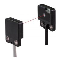
Beam alignment
Placing the emitter and the receiver face to face
along a straight line, move the emitter in the up,
down, left and right directions, in order to deter-
mine the range of the light received condition
with the help of the operation indicator (red).
Then, set the emitter at the center of this range.
Similarly, adjust for up, down, left and right an-
gular movement of the emitter.
Further, perform the angular adjustment for the
receiver also.
Thru-beam type sensor (EX-M2E, EX-M2)
Sensing object
Emitter
Receiver
Operation indicator
(Red)
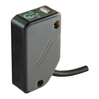
Diffuse reflective type sensor (EX-D200E)
After sensitivity adjustment is made, fit the ad-
juster cap.
Sensing object
Sensor
Adjuster cap
Operation indicator
(Red)
Sensitivity adjuster
٨ Sensitivity adjustment
Ԙ
ԙ
Ԛ
ԛ
Turn the sensitivity adjuster fully counter-
clockwise to the minimum sensitivity posi-
tion, MIN.
Place an object at the required distance
from the sensor, turn the sensitivity adjust-
er gradually clockwise, and find out point
where the sensor changes to the light re-
ceived condition.
The position at the middle of points and
is the optimum sensing position.
Step
Sensitivity adjuster
Description
Remove the object, turn the sensitivity adjuster
further clockwise, and find out point where
the sensor changes to the light received
condition again with only the background.
When the sensor does not go to the light
received condition even if the adjuster is fully
turned clockwise, point is this extreme point.
Optimum position
Note: Use the accessory adjuster screwdriver to turn the distance
adjuster slowly. Turning with excessive force will cause dam-
age the adjuster.
Thank you very much for purchasing Panasonic
products. Please read this Instruction Manual
carefully and thoroughly for the correct and
optimum use of this product. Kindly keep this
manual in a convenient place for quick reference.
Micro Photoelectric Sensor
EX Series
INSTRUCTION
MANUAL
MJE-EXM2 No.0034-43V