Do you have a question about the Panasonic KT4 series and is the answer not in the manual?
Procedures that may lead to death or serious injury if not carried out properly.
Procedures that may lead to injury or damage if not carried out properly.
Explains the components of the model number for the controller.
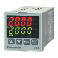
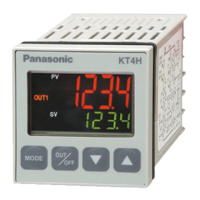
Indicates the PV (input value) and SV (main set value) with LEDs.
Explains the function of various indicator LEDs on the panel.
Describes the function of the control keys on the panel.
Specifies environmental conditions for mounting the controller.
Provides the external dimensions of the controller.
Specifies the required panel cutout dimensions for installation.
Details the dimensions for the current transformer (CT).
Instructions on how to mount the controller vertically to a panel.
General wiring instructions and precautions.
Specifies types of solderless terminals and tightening torque.
Details on using the current transformer for heater burnout alarm.
Sets the Set value (SV) within its limits.
Accesses tuning and output band settings.
Configures PID tuning parameters like AT, proportional band, integral, and derivative times.
Configures proportional cycle and anti-reset windup (ARW).
Sets action points for alarms and heater burnout.
Configures set value lock and other auxiliary functions.
Locks set values to prevent errors and disable tuning.
Sets the SV high and low limit values.
Sets the correction value for the sensor.
Configures communication protocol, speed, parity, and stop bits.
Selects the input type (thermocouple, RTD, DC).
Sets scaling high limit for DC input types.
Sets the scaling low limit value for DC input types.
Selects the decimal point place for DC input.
Sets OUT1 high/low limits and ON/OFF hysteresis.
Configures OUT2 action mode, high/low limits.
Sets overlap/dead band and OUT2 ON/OFF hysteresis.
Selects the type for Alarm 1.
Selects the type for Alarm 2.
Selects Energized/Deenergized status for A1/A2 outputs.
Sets hysteresis for A1 and A2 alarms.
Sets action delayed timer for A1 and A2 alarms.
Selects Reverse (Heating) or Direct (Cooling) control action.
Sets bias value during PID auto-tuning.
Selects output status when input is over/underscale.
Selects function for OUT/OFF key.
Switches between automatic and manual control modes.
Pauses control action or turns output OFF.
Displays the output manipulated variable (MV).
Steps for initial setup, adjustment, locking, and running.
Details the steps for setting Alarm 1 parameters.
Explains how to access output OFF or Auto/Manual control.
Shows how to view the output manipulated variable.
Explains the behavior of OUT1 for heating/cooling and different output types.
Explains the action of the EVT (Heater burnout alarm).
Explains OUT1 ON/OFF action with hysteresis.
Lists input types, ranges, and indications.
Describes different alarm types and their indications.
Selects the type for Alarm 1 and Alarm 2.
Selects the input type (thermocouple, RTD, DC).
Sets scaling limits for DC input types.
Behavior of High limit alarm for A1/A2.
Behavior of Low limit alarm for A1/A2.
Behavior of High/Low limits alarm for A1/A2.
Behavior of Process high/low alarms for A1/A2.
Behavior of alarms with standby function for A1/A2.
Describes OUT1 relay contact action in heating/cooling.
Describes OUT1 non-contact voltage output action.
Describes OUT1 DC current output action.
Describes OUT2 non-contact relay output action.
Describes OUT1 actions with dead band for different output types.
Describes OUT2 action with dead band.
Describes OUT1 actions with overlap band for different output types.
Describes OUT2 action with overlap band.
Explains the PID auto-tuning process and its conditions.
Details mounting, display, accuracy, and input specifications.
Lists input types and their detailed specifications.
Details OUT1 control output specifications.
Specifies A1 output action, hysteresis, and capacity.
Explains control actions (PID, PI, PD, ON/OFF).
Details circuit insulation, voltage, and power specifications.
Specifies ambient conditions, weight, dimensions, and material.
Explains output status for input abnormalities.
Details thermocouple and RTD input ranges and control ranges.
Details DC current/voltage input ranges and control ranges.
Describes burnout detection and self-diagnosis function.
Explains cold junction compensation and power failure countermeasure.
Lists included and separately sold accessories.
Details optional Alarm 2 and Heater burnout alarm specifications.
Details Heating/Cooling control for OUT2.
Details serial communication operations and parameters.
Addresses issues with PV display indications like OFF, flashing, or --.
Addresses issues with key operations, value changes, or setting locks.
Addresses control issues like temperature not rising or output stuck ON/OFF.
| Brand | Panasonic |
|---|---|
| Model | KT4 series |
| Category | Temperature Controller |
| Language | English |