Do you have a question about the Panasonic KT4H and is the answer not in the manual?
Important notes and precautions for safe and correct use of the Panasonic KT4H/B controller.
Details safety warnings and cautions, including risks of death, injury, or damage.
Guidance on preventing misuse of the instrument for weapons of mass destruction.
Specifies environmental conditions and precautions for installing the controller.
Details important precautions and guidelines for wiring the controller correctly.
Covers safety measures during operation, maintenance, and cleaning.
Explains the coding system for different features of the KT4H/B model number.
Guides users on how to read and understand the information on the controller's rated label.
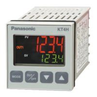
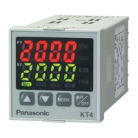
Details the various displays and action indicators on the controller's front panel.
Explains the functions of the operation keys and the tool connector.
Provides detailed physical dimensions of the KT4H/B controller unit.
Specifies the external dimensions of the AKT4H820 tool cable.
Shows the external dimensions for the optional current transformers (AKT4815/AKT4816).
Details the external dimensions of the optional AKT4H801 terminal cover.
Provides instructions on how to pass wires through the terminal cover.
Specifies the required panel cutout dimensions for controller mounting.
Details the steps for mounting and removing the controller from a control panel.
Illustrates the terminal arrangement and provides descriptions for each terminal.
Specifies the type of solderless terminals and their tightening torque for wiring.
Explains how to wire the heater burnout alarm using a current transformer (CT).
Outlines the sequence for setting parameters: Setup, Main, Sub, and Auxiliary modes.
Describes the initial setup required before operating the controller.
Explains how to navigate and set values using the controller's keys.
Details parameters configurable in the Main setting mode, including SV settings.
Lists parameters configurable in the Sub setting mode, such as PID and Auto-tuning.
Covers parameters for auxiliary functions like communication and lock settings.
Details parameters configurable in the Setup mode, including input type and scaling.
Summarizes the key combinations for various operations and mode entries.
Configures the primary set value (SV) for the controller.
Sets the secondary set value (SV2), with conditions for availability.
Sets the tertiary set value (SV3), with conditions for availability.
Sets the quaternary set value (SV4), with conditions for availability.
Selects Auto-tuning or Auto-reset for PID or P/PD control actions.
Sets the proportional band for the OUT1 control output.
Sets the proportional band for the OUT2 control output.
Sets the integral time for the OUT1 control output.
Sets the derivative time for the OUT1 control output.
Sets the ARW value for OUT1 to prevent overshoot in PID control.
Sets the proportional cycle time for the OUT1 control output.
Sets the proportional cycle time for the OUT2 control output.
Sets the action point for the Alarm 1 output.
Sets the action point for the Alarm 2 output.
Sets the heater current value for the Heater burnout alarm.
Sets the heater current value for the Heater burnout alarm 2.
Details the available alarm types and their corresponding setting ranges.
Locks set values to prevent accidental changes.
Corrects input values from the sensor to compensate for deviations.
Selects the communication protocol (Modbus ASCII/RTU, MEWTOCOL).
Assigns a unique instrument number for communication with multiple units.
Sets the communication speed to match the host computer.
Selects the data bit and parity settings for communication.
Selects the number of stop bits for communication.
Sets the minimum response time for communication.
Selects the input type (thermocouple, RTD, DC voltage/current) and temperature unit.
Sets the high limit value for scaling the input signal.
Sets the low limit value for scaling the input signal.
Selects the number of decimal places for DC input types.
Sets the time constant for the PV filter to adjust response delay.
Sets the high limit value for the OUT1 control output.
Sets the low limit value for the OUT1 control output.
Sets the ON/OFF action hysteresis for OUT1.
Selects the cooling action mode for OUT2 (Air, Oil, Water).
Sets the high limit value for the OUT2 control output.
Sets the low limit value for the OUT2 control output.
Sets the overlap band or dead band for OUT1 and OUT2.
Sets the ON/OFF action hysteresis for OUT2.
Selects the action type for Alarm 1 (e.g., high limit, low limit).
Selects the action type for Alarm 2.
Sets the Energized/Deenergized status for Alarm 1.
Sets the Energized/Deenergized status for Alarm 2.
Sets the hysteresis value for Alarm 1.
Sets the hysteresis value for Alarm 2.
Sets the delayed timer for Alarm 1 activation.
Sets the delayed timer for Alarm 2 activation.
Sets the rate at which the SV increases per minute.
Sets the rate at which the SV decreases per minute.
Selects between Reverse (Heating) and Direct (Cooling) control action.
Sets the bias value used during PID auto-tuning.
Configures the function of contact input terminals (DI2).
Selects output status when DC input is over/underscale.
Determines if the OUT/OFF key controls output or Auto/Manual mode.
Selects which displays and indicators are backlit.
Selects the display color for the PV (Process Variable).
Sets the range for PV color changes, used with continuous color modes.
Sets the time until the backlight switches off after no operation.
Maps input terminals to functions based on OUT/OFF key selection.
Describes the steps to follow after powering on the unit for the first time.
Explains how to pause control action or turn off the output of specific units.
Details how to switch between automatic and manual control modes.
Explains how to view the current output MV on the display.
Guides on how to start, perform, and cancel auto-tuning or auto-reset.
Describes how to set up and use the ON/OFF control action.
Explains the P, I, and D actions, and ARW for PID control.
Details the steps for configuring and utilizing alarm outputs.
Lists the available PV display color options and their behavior.
Illustrates how PV color changes based on set point and range.
Shows PV color changes related to alarms and set points.
Explains how auto-reset corrects offset during PD action.
Describes ARW's role in reducing overshoot caused by integral action.
Provides critical notices and warnings regarding the auto-tuning process.
Describes auto-tuning when there's a large initial difference with rising temperature.
Explains auto-tuning when the control is stable or within ±20°C of SV.
Describes auto-tuning when there's a large initial difference with falling temperature.
Explains the behavior of OUT1 for PID, PI, PD, and P control actions.
Details the ON/OFF control action for OUT1, including hysteresis.
Describes the action taken when a heater burnout is detected.
Explains various alarm action types (high limit, low limit, etc.).
Details how to enable and set up Heating/Cooling control for OUT2.
Illustrates OUT2 reverse action with relay contact output for OUT1.
Shows OUT2 reverse action with non-contact voltage output for OUT1.
Depicts OUT2 reverse action with DC current output for OUT1.
Illustrates OUT2 reverse action using relay contact output.
Shows OUT2 reverse action using non-contact voltage output.
Explains the meaning of indicator lights for OUT1 and OUT2.
Details dead band settings for OUT2 reverse action.
Explains how to set the dead band for OUT2.
Details how to enable and set up Heating/Cooling control for OUT2.
Illustrates OUT2 direct action with relay contact output for OUT1.
Shows OUT2 direct action with non-contact voltage output for OUT1.
Depicts OUT2 direct action with DC current output for OUT1.
Illustrates OUT2 direct action using relay contact output.
Shows OUT2 direct action using non-contact voltage output.
Explains indicator status for OUT2 direct action.
Details overlap band settings for OUT2 reverse action.
Explains how to set the overlap band for OUT2.
Illustrates OUT2 reverse action with overlap band using Relay OUT1.
Shows OUT2 reverse action with overlap band using Non-Contact OUT1.
Depicts OUT2 reverse action with overlap band using DC Current OUT1.
Illustrates OUT2 reverse action with overlap band using Relay OUT2.
Shows OUT2 reverse action with overlap band using Non-Contact OUT2.
Explains indicator status for OUT2 reverse action with overlap band.
Details dead band settings for OUT2 direct action.
Explains how to set the dead band for OUT2.
Illustrates OUT2 direct action with dead band using Relay OUT1.
Shows OUT2 direct action with dead band using Non-Contact OUT1.
Depicts OUT2 direct action with dead band using DC Current OUT1.
Illustrates OUT2 direct action with dead band using Relay OUT2.
Shows OUT2 direct action with dead band using Non-Contact OUT2.
Explains indicator status for OUT2 direct action with dead band.
Details overlap band settings for OUT2 direct action.
Explains how to set the overlap band for OUT2.
Illustrates OUT2 direct action with overlap band using Relay OUT1.
Shows OUT2 direct action with overlap band using Non-Contact OUT1.
Depicts OUT2 direct action with overlap band using DC Current OUT1.
Illustrates OUT2 direct action with overlap band using Relay OUT2.
Shows OUT2 direct action with overlap band using Non-Contact OUT2.
Explains indicator status for OUT2 direct action with overlap band.
Illustrates SV behavior when rise and fall rates are set to zero.
Shows SV behavior with a 60°C/min rise rate and 0°C/min fall rate.
Depicts SV behavior with 60°C/min rise and 30°C/min fall rates.
Explains SV rate adjustment when SV is greater than PV.
Explains SV rate adjustment when SV is less than or equal to PV.
Illustrates the system configuration for communication with multiple controllers.
Provides wiring examples for connecting to host computers or PLCs.
Shows the wiring diagram for connecting the controller to a PLC via RS-485.
Provides instructions on connecting shielded wires for noise reduction.
Explains when and how to use a terminator resistor in communication lines.
Step to enter the Auxiliary Function Setting mode.
Entry point for configuring auxiliary functions.
Selects the communication protocol: Modbus ASCII, RTU, or MEWTOCOL.
Assigns a unique instrument number for communication.
Sets the communication speed (bps).
Configures data bits and parity for communication.
Selects the number of stop bits for communication.
Sets the minimum response time for communication.
Programming notices for the master side regarding communication timing.
Details synchronization procedures on the slave side for communication.
Defines the data format for the MEWTOCOL communication protocol.
Explains the structure of RD and WD commands in MEWTOCOL.
Describes the header code used in MEWTOCOL commands.
Explains the instrument number used for addressing slaves.
Lists the command codes used in MEWTOCOL.
Details the command codes for reading (RD) and writing (WD).
Specifies the data code used in MEWTOCOL.
Explains the BCC calculation and its purpose.
Describes the terminator used to end MEWTOCOL commands.
Lists and explains the error codes used in MEWTOCOL communication.
Example of a message for reading PV data.
Example of a message for reading SV data.
Example of a message for setting SV data.
Lists data items accessible with the RD command.
Lists data items configurable via RD/WD commands.
Commands for setting SV rise and fall rates.
Command to control the output state (ON/OFF).
Command to switch between Auto and Manual control.
Command to select the input type.
Command to select control action direction.
Commands to control the display backlight.
Commands to set the PV display color.
Reads the status flag indicating controller states.
Notes on data conversion, addressing, and command restrictions.
Details scenarios leading to negative acknowledgements (error codes).
Describes the available transmission modes for Modbus (ASCII and RTU).
Details the configuration and message structure for Modbus ASCII mode.
Explains the calculation and use of LRC for error detection in ASCII mode.
Provides examples of request and response messages in ASCII mode.
Example of reading SV data using Modbus RTU.
Example of setting SV data using Modbus RTU.
Details the message configuration for Modbus RTU mode.
Explains the slave address for Modbus RTU communication.
Lists and explains the function codes used in Modbus RTU.
Explains the CRC-16 calculation for error detection in RTU mode.
Provides examples of request and response messages in RTU mode.
Example of reading SV data via Modbus RTU at address 1.
Example of setting SV data via Modbus RTU at address 1.
Lists data items readable using Modbus function code 03H.
Lists data items configurable using Modbus functions 03H/06H.
Commands to set SV rise and fall rates.
Command to control the output state.
Command to switch between Auto and Manual control.
Command to select the input type.
Command to select control action direction.
Commands to control the display backlight.
Commands to set the PV display color.
Reads the status flag indicating controller states.
Notes on data conversion, addressing, and command restrictions.
Details scenarios leading to negative acknowledgements (error codes).
Provides detailed specifications for the controller's features and performance.
Specifies mounting type and requirements.
Details specifications for PV, SV, and MEMO displays.
Specifies the accuracy for setting and indication across various input types.
Details the supported input types, ranges, and associated specifications.
Specifies the types and capacities of the OUT1 control output.
Details specifications for PID, PI, PD, P, and ON/OFF control actions.
Describes the insulation configuration between various circuits.
Specifies the allowable supply voltage range.
Indicates the typical power consumption of the unit.
Specifies the allowable ambient temperature range.
Specifies the allowable ambient humidity range.
Provides the weight of the controller unit.
Summarizes the external dimensions of the controller unit.
Details the material used for the controller case.
Specifies the available colors for the controller case.
Lists the attached functions of the controller, like power failure countermeasure.
Describes how input abnormalities affect output status and indications.
Defines indication and control ranges for thermocouple, RTD, and DC inputs.
Explains the indications shown during the warm-up period after power-on.
Details the procedure for switching between Auto and Manual control.
Describes operations possible via the tool port and the required cable.
Details specifications for the optional Alarm 2 output.
Specifies the optional Heater Burnout Alarm functionality.
Details specifications for the optional Heating/Cooling control for OUT2.
Details serial communication capabilities and restrictions.
Specifies parameters for the communication line (RS-485).
Lists selectable communication speeds.
Lists selectable data bit and parity options.
Lists selectable stop bit options.
Sets the response time for serial communication.
Allows selection between Modbus ASCII, RTU, and MEWTOCOL.
Details contact input functions and their wiring.
Provides solutions for common display indications like OFF, flashing, or ERR.
Guides on how to check if thermocouple, RTD, or DC voltage sensors are burnt out.
Provides steps to check for disconnected input signal wires.
Addresses issues with abnormal or unstable PV display indications.
Provides solutions for the [ERR 1] indication on the PV display.
Solutions for problems with key operations, value changes, and setting indications.
Addresses problems with temperature not rising or outputs remaining ON/OFF.
Steps to diagnose and fix communication connection and wiring issues.
Solutions for communication issues where NAK responses are received.
Lists the issue dates and corresponding manual numbers for revisions.
Details the changes made in each revision of the manual.
Provides contact information for Panasonic Industrial Devices SUNX Co., Ltd.
Link to the global support website for additional information.
| Brand | Panasonic |
|---|---|
| Model | KT4H |
| Category | Temperature Controller |
| Language | English |