57
13. Specifications
13.1 Standard specifications
Mounting : Flush
Setting : Input system using membrane sheet key
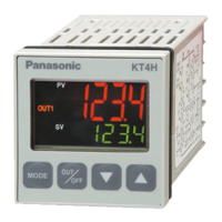
Display PV display : 11-segment backlight LCD Red/Green/Orange, character size 12.0 x 5.4mm (H x W)
SV display : 11-segment backlight LCD Green, character size 6.0 x 3.5mm (H x W)
MEMO display : 11-segment backlight LCD Green, character size 4.8 x 2.8mm (H x W)
Action indicators: Backlight Orange
Accuracy (Setting and Indication):
Thermocouple : Within 0.2% of each input span 1digit, or within 2 (4 ),
whichever is greater
However R, S inputs, 0 to 200 (0 to 400 ): Within 6 (12 )
B input, 0 to 300 (600 ): Accuracy is not guaranteed
K, J, E, T, N inputs, less than 0 (32 ): Within 0.4% of input span 1digit
RTD : Within 0.1% of each input span 1digit, or within 1 (2 ),
whichever is greater
DC current : Within 0.2% of each input span 1digit
DC voltage : Within 0.2% of each input span 1digit
Input sampling period : 0.25 seconds
Input Thermocouple : K, J, R, S, B, E, T, N, PL- , C (W/Re5-26)
External resistance, 100 or less
(However, B input: External resistance, 40 or less)
RTD : Pt100, JPt100, 3-wire system
Allowable input lead wire resistance (10 or less per wire)
DC current : 0 to 20mA DC, 4 to 20mA DC
Input impedance: 50 [50 shunt resistor (sold separately) must be
connected between input terminals.]
Allowable input current, 50mA or less [When 50 shunt resistor (sold
separately) is used]
DC voltage : 0 to 1V DC Input impedance (1M or more)
Allowable input voltage (5V DC or less)
Allowable signal source resistance (2k or less)
: 0 to 5V DC, 1 to 5V DC, 0 to 10V DC Input impedance (100k or more)
Allowable input voltage (15V DC or less)
Allowable signal source resistance (100 or less)
Control output (OUT1)
Relay contact : 1a, Control capacity 3A 250V AC (resistive load)
1A 250V AC (inductive load cosø=0.4)
Electrical life, 100,000 cycles
Non-contact voltage (For SSR drive): 12V DC 15%, Maximum 40mA (short circuit protected)
DC current : 4 to 20mA DC, Load resistance, Maximum 550
Alarm 1 output
Action : ON/OFF action
Hysteresis : 0.1 to 100.0 ( ), or 1 to 1000 (Default: 1.0 )
Output : Relay contact 1a
Control capacity, 3A 250V AC (resistive load) Electrical life, 100,000 cycles
Control action
PID action (with auto-tuning function)
PI action: When derivative time is set to 0
PD action (with auto-reset function): When integral time is set to 0
P action (with auto-reset function): When derivative and integral time are set to 0.
ON/OFF action: When proportional band is set to 0 or 0.0
OUT1 proportional band : 0 to 1000 (2000 ), 0.0 to 1000.0 ( ) or 0.0 to 100.0%
(ON/OFF action when set to 0 or 0.0) (Default: 10 )