26
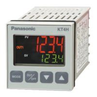
8.4 Changing PV color
(1) In the PV/SV display mode, press key for approximately 3 seconds while pressing key.
The unit proceeds to the Setup mode, and the Input type selection item appears.
(2) Press key several times until [54] PV color selection item appears.
(3) Select the PV color with or key. (Table 8.4-1)
(4) If “PV color changes continuously ( or )” is selected during [54] PV color selection, set the
value of [55] PV color range. (Fig. 8.4-1) (Fig. 8.4-2)
(5) Press key several times to revert to the PV/SV display mode.
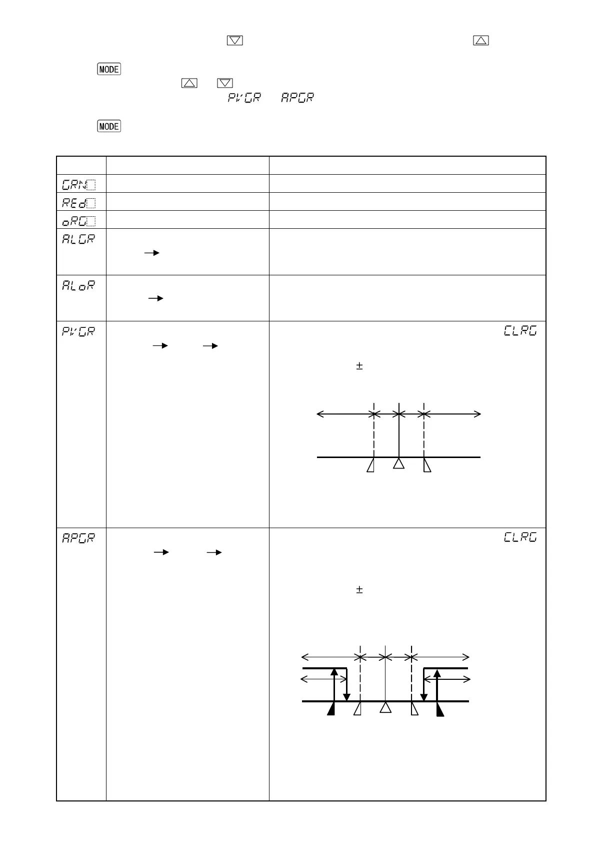
(Table 8.4-1)
Setting
Function PV color
Green Constantly green
Red Constantly red
Orange Constantly orange
When Alarm 1 or Alarm 2 is ON:
Green Red
When alarm OFF: Green
When Alarm 1 or Alarm 2 is ON, the PV color turns
from green to red.
When Alarm 1 or Alarm 2 is ON:
Orange Red
When alarm OFF: Orange
When Alarm 1 or Alarm 2 is ON, the PV color turns
from orange to red.
PV color changes continuously
(Orange Green Red)
PV color changes depending on color range setting ( ).
• PV is lower than [SV-PV color range]: Orange
• PV is within [SV PV color range]: Green
• PV is higher than [SV+PV color range]: Red
Hys: Set point of PV color range
(Fig. 8.4-1)
PV color changes continuously
(Orange Green Red),
and at the same time Alarm 1 or
Alarm 2 is ON (Red).
PV color changes depending on color range setting ( ).
When Alarm 1 or Alarm 2 is on, PV display turns red.
• PV is lower than [SV-PV color range]: Orange
• PV is within [SV PV color range]: Green
• PV is higher than [SV+PV color range]: Red
• Alarm1 or Alarm 2 is ON: Red
Hys: Set point of PV color range
A1: Alarm 1 set point (in the case of High limit alarm)
A2: Alarm 2 set point (in the case of Low limit alarm)
(Fig. 8.4-2)
Hys
Hys
SV
Orange Green
Red
Hys
Hys
SV
A1
A2
Orange
Green
Red
Red
Red