48
(2) Error check of ASCII mode
After calculating LRC (Longitudinal Redundancy Check) from the slave address to the end of data,
the calculated 8-bit data is converted to two ASCII characters and are appended to the end of message.
How to calculate LRC
1
Create a message in RTU mode.
2
Add all the values from the slave address to the end of data. This is assumed as X.
3
Make a complement for X (bit reverse). This is assumed as X.
4
Add a value of 1 to X. This is assumed as X.
5
Set X as an LRC to the end of the message.
6
Convert the whole message to ASCII characters.
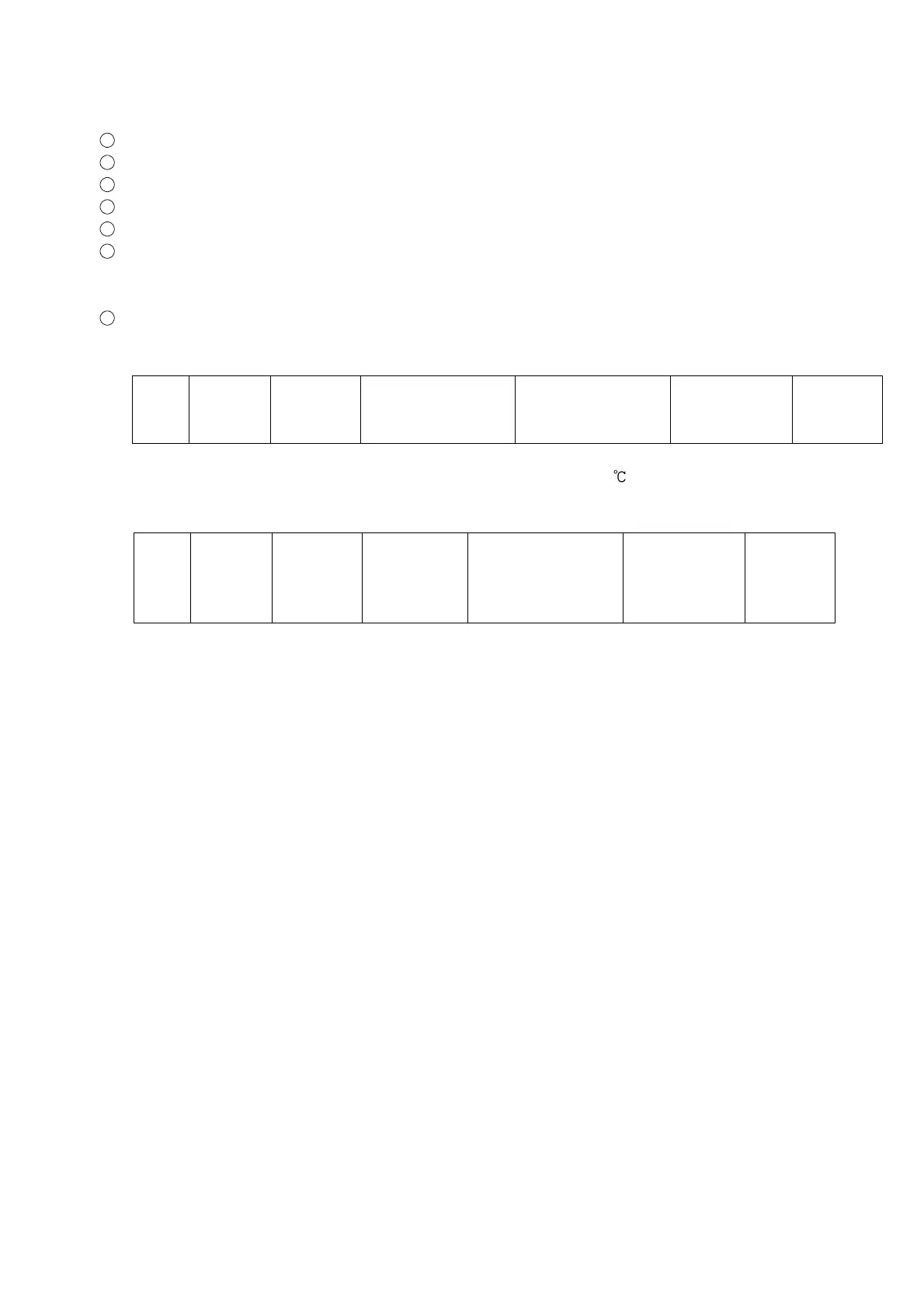
(3) Message example of ASCII mode
1
Reading (Address 1, PV)
• A request message from the master
The number of data means the data item to be read, and it is fixed as 1 (30H 30H 30H 31H).
Header
(3AH)
Slave
address
(30H 31H)
Function
code
(30H 33H)
Data item
[0080H]
(30H 30H 38H 30H)
Number of data
[0001H]
(30H 30H 30H 31H)
Error check
LRC
(37H 42H)
Delimiter
CR+LF
(0DH 0AH)
• Response message from the slave in normal status (When PV=600 [0258H])
The number of response byte means the number of bytes of the data which has been read,
and it is fixed as 2 (30H 32H).
Header
(3AH)
Slave
address
(30H 31H)
Function
code
(30H 33H)
Number of
response byte
[02H]
(30H 32H)
Data
[0258H]
(30H 32H 35H 38H)
Error check
LRC
(41H 30H)
Delimiter
CR+LF
(0DH 0AH)