22
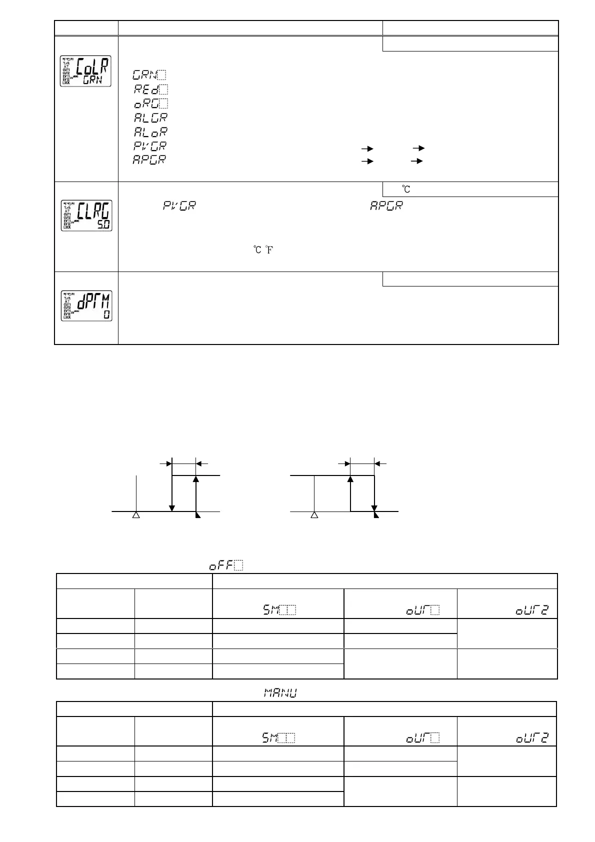
Character Name, Function, Setting range Default value
PV color selection
Green
[54]
• Selects PV display color. (Refer to Section “8.4 Changing PV color” on p.26.)
• : Green
: Red
: Orange
: When Alarm 1 or Alarm 2 is ON, PV color turns from green to red.
: When Alarm 1 or Alarm 2 is ON, PV color turns from orange to red.
: PV color changes continuously (Orange Green Red).
: PV color changes continuously (Orange Green Red), and at the same time
Alarm 1 or Alarm 2 is ON (Red).
PV color range setting
5.0
[55]
• When (PV color changes continuously) or (PV color changes
continuously, and at the same time Alarm 1 or Alarm 2 is ON; Red) is selected during PV
color selection, the value of green PV color range can be set.
• Setting range: 0.1 to 100.0 ( ) DC voltage, current input: 1 to 1000 (The placement of
the decimal point follows the selection.)
Backlight time setting
0 minutes
[56]
• Sets time to backlight from no operation status until backlight is switched off.
When set to 0, the backlight remains ON.
Backlight relights by pressing any key while backlight is OFF.
• Setting range: 0 to 99 minutes
[Alarm Energized/Deenergized]
When [Alarm Energized] is selected, the alarm output (between terminals 3–4, or 5–6) is conductive (ON) while
EVT1 (or EVT2) indicator is lit. The alarm output is not conductive (OFF) while EVT1 (or EVT2) indicator is not lit.
When [Alarm Deenergized] is selected, the alarm output (between terminals 3–4, or 5–6) is not conductive (OFF)
while EVT1 (or EVT2) indicator is lit. The alarm output is conductive (ON) while EVT1 (or EVT2) indicator is not lit.
[This function is not available for the Heater burnout alarm (optional).]
High limit alarm (when Energized is set) High limit alarm (when Deenergized is set)
“A1” means Alarm 1.
(Fig. 6.8-2) (Fig. 6.8-3)
[Contact input function] Actions depend on OUT/OFF key function selection.
When OUT/OFF function ([52] in the Setup mode) is selected
Connecting terminal number Contact input function: [50] in the Setup mode
Between 17-18
(DI1-COM)
Between 16-18
(DI2-COM)
Set value memory external
selection ( )
OUT/OFF external
selection 1 ( )
OUT/OFF external
selection 2 ( )
Open Open SV SV
Closed Open SV2 SV2
SV
Open Closed SV3
Closed Closed SV4
Control output OFF Control output OFF
When Auto/Manual control function ([52] in the Setup mode) is selected
Connecting terminal number Contact input function: [50] in the Setup mode
Between 17-18
(DI1-COM)
Between 16-18
(DI2-COM)
Set value memory external
selection ( )
OUT/OFF external
selection 1 ( )
OUT/OFF external
selection 2 ( )
Open Open SV SV (Automatic control)
Closed Open SV2 SV2 (Automatic control)
SV
(Automatic control)
Open Closed SV3
Closed Closed SV4
Manual control Manual control
OFF
ON
A1 hysteresis
SV setting + A1 set point
OFF
ON
SV setting
+ A1 set point
A1 hysteresis
 Loading...