59
[Burnout]
When the thermocouple or RTD input is burnt out, OUT1 and OUT2 are turned OFF (for DC current output
type, OUT1 low limit value) and the PV display flashes “ ”.
However, for the manual control, the preset MV (manipulated variable) is outputted.
When the DC current or DC voltage input is disconnected, PV display flashes “ ” for 4 to 20mA DC and
1 to 5V DC inputs, and “ ” for 0 to 1V DC input.
For 0 to 20mA DC, 0 to 5V DC and 0 to 10V DC inputs, the PV display indicates the value corresponding with
0mA or 0V input.
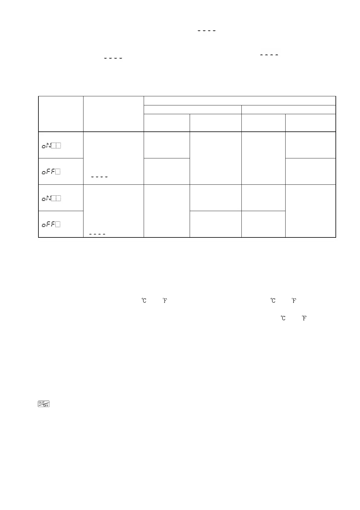
[Input abnormality indication]
Output status
OUT1 OUT2
Output status
selection when
input abnormal
Contents and
Indication
Direct(cooling)
action
Re
action
Direct
action
Reverse
action
ON (20mA) or
OUT1 high
limit value (*)
ON or
OUT2 high
limit value (*)
Overscale
Measured value
has exceeded
Indication range
high limit value.
" " flashes.
OFF (4mA) or
OUT1 low
limit value
OFF (4mA) or
OUT1 low limit
value
OFF or
OUT2 low
limit value
OFF or
OUT2 low
limit value
ON (20mA) or
OUT1 high limit
value (*)
ON or
OUT2 high
limit value (*)
Underscale
Measured value
has dropped below
Indication range
low limit value.
" " flashes.
OFF (4mA) or
OUT1 low
limit value
OFF (4mA) or
OUT1 low limit
value
OFF or
OUT2 low
limit value
OFF or
OUT2 low
limit value
Only for DC input and DC current output type, [Output status selection when input abnormal] is usable.
For manual control, the preset manipulated variable (MV) is outputted.
(*) Outputs a value between OFF (4mA) and ON (20mA) or between OUT1 (or OUT2) low limit value and
OUT1 (or OUT2) high limit value, depending on deviation.
[Indication range and Control range]
Thermocouple input:
[Input range low limit value -50 (100 )] to [Input range high limit value +50 (100 )]
RTD input:
[Input range low limit value -Input span x 1%] to [Input range high limit value +50 (100 )]
DC current, voltage input:
[Scaling low limit value -Scaling span x 1%] to [Scaling high limit value +Scaling span x 10%)
[Warm-up indication]
After the power supply to the instrument is turned on, the PV display indicates the sensor input type, and
SV display indicates input range high limit value (for thermocouple, RTD) or Scaling high limit value (for DC
input) for approx. 3 seconds.
[Auto/Manual control switching]
Select “Auto/Manual control” during [52] OUT/OFF key function selection in the Setup mode, then press the
key in the PV/SV display mode. Auto/Manual control can be switched.
[Tool port communication]
By connecting to the tool connector of the KT4H/B, the following operations can be conducted from the
external computer.
(1) Reading and setting of SV, PID and various set values
(2) Reading of PV and action status
(3) Function change
Communication interface: C-MOS level (Cannot be used with Serial communication option)
Cable for use: Tool Cable (AKT4H820)