Do you have a question about the Panasonic KX-DT543 and is the answer not in the manual?
General safety measures and warnings for handling electrical equipment.
Guidelines and cautions for using lead-free solder in repairs.
High-level block diagram illustrating the main system components and connections.
Detailed explanation of various circuit functionalities within the device.
Explanation of data exchange protocols between the phone and PBX.
Description of DXDP port communication and power feeding for slave devices.
Details on analog circuits for speakerphone and handset audio.
Role of ASIC IC300 in data communication and audio signal exchange.
Functionality of ASIC IC150 for key, LED, EHS, and headset detection.
Explanation of the key detection matrix and HOOK switch functionality.
How IC150 controls the lighting of various LEDs on the device.
Functionality of the EHS circuit and its control by IC150.
Overview of the power supply distribution and voltage rails within the phone.
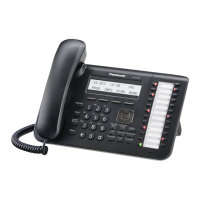
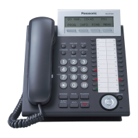
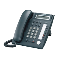
Identification and location of buttons, display, and indicators on the front panel.
Instructions for connecting the telephone line cord and headset.
Procedure for entering test mode and required setup devices.
Steps for verifying the functionality of keys and LEDs during testing.
Flowchart for diagnosing and resolving 'No Operation' issues.
Troubleshooting steps for ASIC IC300 failure.
Troubleshooting steps for problems with the LCD display not functioning.
Troubleshooting steps for issues with DXDP communication.
General troubleshooting guide for audio-related issues.
Troubleshooting steps for handset receive and send problems.
Troubleshooting steps for headset receive and send problems.
Troubleshooting steps for speaker-phone and ringer malfunctions.
Troubleshooting guide for situations where LEDs do not light up.
Troubleshooting steps for EHS (Plantronics) communication issues.
Troubleshooting steps for Jabra EHS communication issues.
Step-by-step guide for removing the main and operation boards.
Instructions for the proper removal and reassembly of the LCD module.
Guidance on routing and securing lead wires during assembly.
Pinout and terminal descriptions for ICs, transistors, and diodes.
Detailed procedure for replacing flat package ICs.
First part of the schematic diagram for the main board.
Second part of the schematic diagram for the main board.
Schematic diagram detailing the operation board circuitry.
Visual representation of clock and communication signal patterns.
Waveforms illustrating communication and reset signal behaviors.
Waveforms depicting DPT-PBX signal transmission and reception.
Waveforms related to LCD clock and communication signals.
Waveforms illustrating DXDP signal transmission and reception.
Waveforms for EHS and Jabra communication signals.
Component placement diagram for the main printed circuit board.
Component layout on the underside of the main printed circuit board.
Component placement diagram for the operation board.
Component layout diagram for the microphone board.
Pinout and function data for integrated circuits (IC410, IC300, IC150).
List and illustration of cabinet parts and electrical components.
List of included accessories and packaging materials.
List of components specifically for the main printed circuit board.
List of components specifically for the operation board.
| Speakerphone | Yes |
|---|---|
| Handset type | Wired handset |
| Product type | IP Phone |
| Product color | Black |
| Number of programmable keys | 24 |
| Lines quantity | - lines |
| Phonebook capacity | - entries |
| Number of VoIP accounts | - |
| Number of handles included | 1 pc(s) |
| Harmonized System (HS) code | 85171800 |