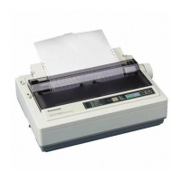
Do you have a question about the Panasonic KX-P1150 - KX-P 1150 B/W Dot-matrix Printer and is the answer not in the manual?
| Print Method | Dot-matrix |
|---|---|
| Resolution | 240 x 216 dpi |
| Interface | Parallel |
| Noise Level | 55 dB |
| Paper Handling | Tractor feed, friction feed |
| Number of Pins | 9 |
Explains basic printer operation and print modes.
Describes service functions for testing and adjusting the printer.
Instructions for removing the printer covers.
Steps for removing the printing mechanism components.
Procedure to remove the main circuit board.
Steps to remove the power supply board.
Instructions for removing and replacing the printhead.
Steps to remove the carriage assembly and its parts.
Instructions for removing the platen and ejection roller assembly.
Procedure for removing the tractor drive assembly.
Detailed procedure for adjusting the printhead gap.
Guide for adjusting the print timing using test patterns.
Explains the carriage drive mechanism and its components.
How paper thickness affects copy count.
Details on the printhead construction and operation.
Overview of the paper feed system using a DC pulse motor.
How the mechanical switch detects paper out.
Overview of switches, circuits, and control panel functions.
Introduces the power supply and circuitry.
Diagram of CPU, Gate Array, ROM, RAM, and peripherals.
Explains the chopper drive circuit for the carriage motor.
Details the drive block for the line feed motor.
Describes the drive block for printhead pins and thermistor.
Details the control panel switches and LEDs.
Explains the reset circuit and EEP ROM function.
Diagram showing connections between main boards and components.
Lists the names and applications of various connectors.
Details the pin assignments for different connectors.
Chart of logic symbols and truth tables.
Pin configuration diagrams for CPU and Gate Array.
Detailed pin assignment for the CPU.
Schematic for IC203.
Schematic for IC205.
Schematic for the power supply board.
Exploded view and parts list for the printer cabinet.
Exploded view and parts list for tractor and carriage.
Exploded view and parts list for the printer chassis.
Parts list and diagram for the control panel board.




 Loading...