Do you have a question about the Panasonic KX-T7765X and is the answer not in the manual?
Precautions for qualified repair personnel to prevent hazards.
Explanation of lead-free solder usage and precautions for servicing.
Step-by-step guide for mounting and connecting the doorphone unit.
Provides pinout details for key electronic components.
Explains the functional logic of the doorphone's call and conversation circuits.
Identifies component placement on the main circuit board.
Highlights critical components with special safety characteristics requiring manufacturer-specified parts.
Visual guide to the physical components and their locations.
Lists included accessories and packaging contents.
Detailed list of available replacement parts for the unit.
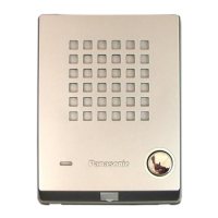
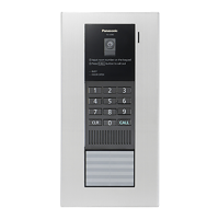
This document is a service manual for the Panasonic Easa-Phone Model No. KX-T7765X, designed for use in Asia, Oceania, the Middle East, Africa, and Latin America. It provides comprehensive information for experienced repair technicians to safely and effectively service the device.
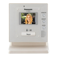
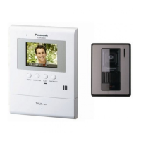
The primary function of the KX-T7765X Easa-Phone is to serve as a doorphone, facilitating communication between an outdoor unit and an indoor adaptor. Its core operation involves a call circuit and a conversation circuit. When the call switch (S1) on the doorphone is pressed, it creates a short circuit between terminals 1 and 2 through resistor R7, signaling a call to the doorphone adaptor. For conversation, the voice signal from the microphone is amplified through transistors Q1 and Q2, then routed through diode D1 and transformer T1 to the doorphone adaptor. Conversely, the received voice signal from the adaptor is directed to the speaker via terminal 1 and transformer T1.
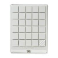
Usage features of the doorphone include its straightforward installation process. The device is designed to be separated into two halves by loosening a single screw. Wires are passed through a hole in the base cover, which is then attached to a wall using two screws. The wires are connected to screws located in the front cover, and finally, the two halves are re-attached, and the screw is re-inserted. The manual also provides guidance for different installation scenarios, such as when a doorphone plate has already been fixed to the wall or when the doorphone is to be installed directly onto the wall.
Maintenance features are extensively covered, emphasizing safety and proper repair techniques. The manual explicitly states that service information is intended for experienced repair technicians and warns against non-technical individuals attempting repairs due to potential hazards like electric shock or fire. It stresses that repair services must adhere to the provided repair technology information and that products or parts should not be remodeled. If a lead wire assembly is supplied as a repair part, it must be replaced entirely. For FASTON terminals, straight plugging and unplugging are crucial.
A significant portion of the maintenance section is dedicated to handling static-sensitive components like ICs and LSIs. Precautions include covering plastic parts boxes with aluminum foil, grounding soldering irons, using a conductive mat on the worktable, and avoiding grasping IC or LSI pins with bare fingers.
The manual also provides detailed instructions regarding lead-free (PbF) solder, which is used in the manufacturing process of this model. It notes that PbF solder has a higher melting point (50° ~ 70°F or 30° ~ 40°C) compared to standard leaded (Pb) solder. Technicians are advised to use a soldering iron with temperature control, set to 700° ± 20°F (370° ± 10°C). Caution is advised against prolonged heating of the PCB to prevent solder splash or damage. It also warns that PbF solder tends to splash if heated much higher than its melting point (approximately 1100°F or 600°C). When applying PbF solder to double-layered boards, technicians must check the component side for excess solder that might flow to the opposite side. The manual recommends specific PbF solder wire sizes: 0.3mm, 0.6mm, and 1.0mm, and suggests using Sn+Ag+Cu, Sn+Cu, or Sn+Zn+Bi types, advising technicians to check manufacturers' instructions for melting points and precautions.
Disassembly and assembly instructions are clearly outlined, starting with the removal of screws to access the rear cabinet and then the P.C. Board. The manual includes exploded views and replacement parts lists, detailing cabinet and electrical parts, accessories, and packing materials, as well as main P.C. Board components. Each part is identified with a reference number, part number, and description.
Important safety notices are highlighted throughout the manual, particularly for components marked with a specific symbol, indicating their critical importance for safety. When replacing these components, only manufacturer-specified parts must be used. The manual also clarifies that DC voltage measurements are taken with an oscilloscope or tester with a ground and that schematic diagrams and circuit boards may be modified due to technological advancements. Resistor and capacitor specifications, including types, wattages, and voltages, are also provided for accurate component replacement. The "RTL" (Retention Time Limited) marking for certain parts indicates that they will be available for a limited period after production discontinuation, emphasizing the importance of timely procurement for repairs.
| Type | Corded |
|---|---|
| Number of Lines | 1 |
| Speakerphone | Yes |
| Intercom | Yes |
| Call Waiting | Yes |
| Caller ID | Yes |
| Ringer Volume Control | Yes |
| Wall Mountable | Yes |
| Redial | Yes |
| Flash | Yes |
| Lines | 1 |
| Speed Dial | Yes |
| Headset Jack | No |
| Power Supply | AC |