8
KX-T7765X
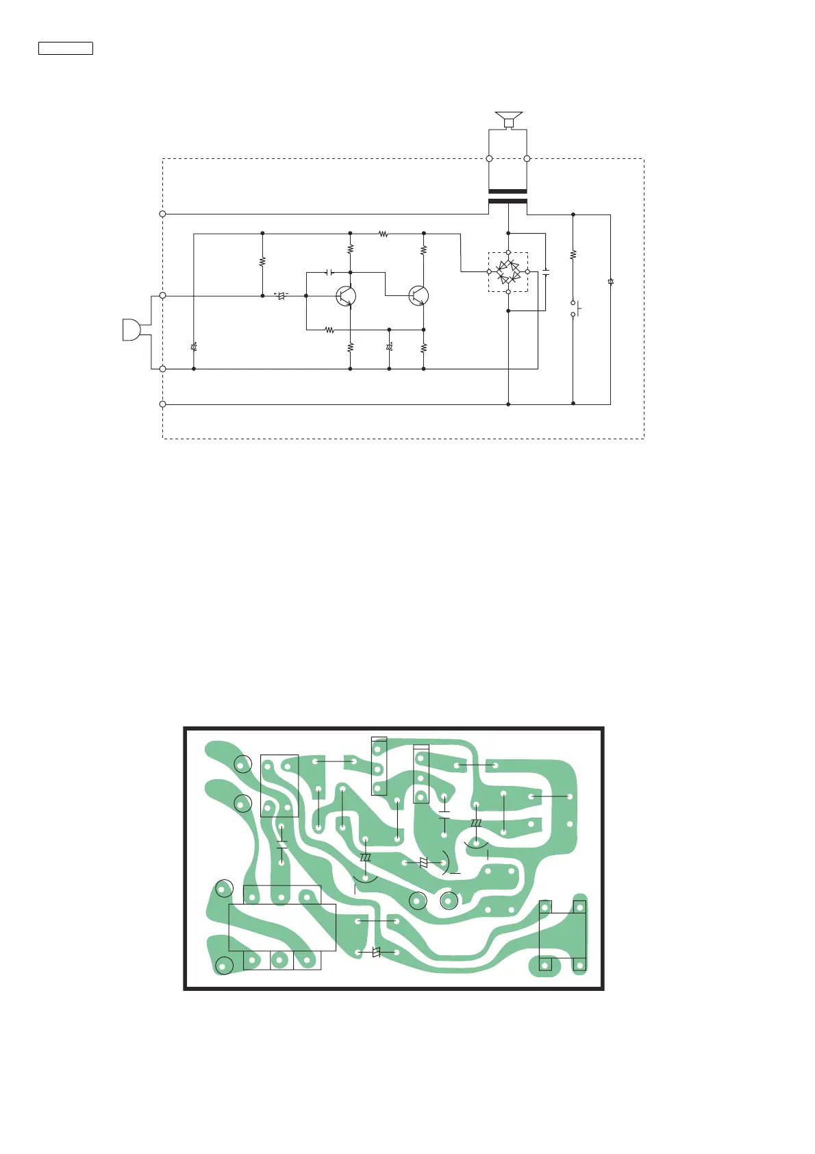
7 Schematic Diagram
7.1. Circuit Operation
1. Call circuit
Depressing switch S1 causes terminals 1 and 2 to be shorted through R7, therefore a call is detected at the doorphone
adaptor side.
2. Conversation
The transmited voice signal is sent to the doorphone adaptor via the following path.
Mic → Q1, 2 → (Mic amp.) → D1 → T1 → Doorphone adaptor.
The received voice signal is received at the SP via the terminal 1 → T1.
Note:
1. S1: Call switch.
8 Printed Circuit Board
8.1. Component View
R6
270
T
M(+)
M(-)
R
M1C
C1
100
R1
2.2K
R2
2.2K
R4
150
C4
Q2Q1
10
16V
R8
150
R7
SP
S(-)
T1
4
D1
6
312
S(+)
1K
C6
1
50V
(NP)
S1
Call SW
C5
M0.047
C2
C3
M0.0047
R3
1K
R5
22K
50V 1
10V
KX-T7765X SCHEMATIC DIAGRAM
1.37V
2.75V
RECT
0.08V
MIC AMP
0.73VMIC AMP
0.69V
!"#$"%&%'*,&/
:;