Do you have a question about the Panasonic KX-TS550MEB and is the answer not in the manual?
Recommendations for lead-free solder types and sizes for product repair.
Instructions for safe and compliant repair work, including avoiding modifications and proper terminal handling.
Measures to prevent damage to ICs and LSIs from static discharge during repair.
Caution regarding the danger of explosion if batteries are replaced incorrectly and disposal instructions.
Step-by-step guide for connecting the telephone line, handset, and setting selectors.
Instructions for initiating and completing phone calls, including redialing and volume adjustment.
Procedure for responding to incoming calls and ending conversations.
How to handle incoming calls when already on a call using the Flash button.
Using the Tone button to access services requiring DTMF dialing from pulse lines.
General tips and common symptoms with their corresponding cures for troubleshooting the telephone.
Diagnostic flowchart for identifying and resolving issues related to pulse dialing functionality.
Troubleshooting steps and checks for issues with the handset's dial tone and signal transmission.
Diagnostic flowchart for identifying and resolving issues with DTMF signal generation and output.
Troubleshooting steps and checks for issues with the ringer not functioning correctly.
Procedure to test IC1 functionality related to key input and signal oscillation.
Explanation of how the telephone line connects and the pulse dialing circuit generates dial pulses.
Description of the DTMF signal generation and its path to the line and handset speaker.
How the unit is powered from the line and the function of the redial back-up circuit.
Replacement parts for the telephone base unit, including cabinets, buttons, and buzzers.
List of components for the main printed circuit board, such as ICs, transistors, diodes, and resistors.
Details of included accessories like cords, handset, and instruction books, plus packing materials.
Identification and part numbers for tapping screws used in the product assembly.
A section for notes or remarks related to the schematic diagrams.
Visual representation of component placement on the main circuit board.
View of the main circuit board's solder side, showing component layout and jumper locations.
View of the operation circuit board's solder side, illustrating key connections and layout.
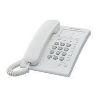
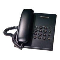
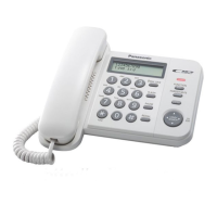
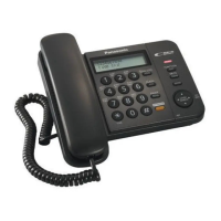
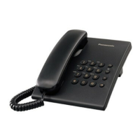
| Type | Corded Telephone |
|---|---|
| Color | Black |
| Speakerphone | No |
| Volume Control | Yes |
| Caller ID | No |
| Redial Function | Yes |
| Phonebook entries | No |
| Wall Mountable | Yes |
| Call Waiting | Yes |
| Ringer Volume Control | Yes |
| Handset Volume Control | Yes |
| Phonebook | No |
| Display | No |
| Dialing Type | Pulse/Tone |
| Weight | 800 g |
| Power Source | Phone Line |
| Design | Tabletop/Wall mountable |