Do you have a question about the Panasonic KX-TS600MXB and is the answer not in the manual?
Details on recommended lead-free solder types and sizes for repair.
Guidance on identifying PCBs manufactured with lead-free solder.
Instructions for installing and replacing the unit's batteries.
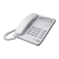
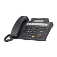
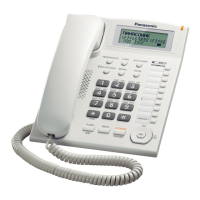
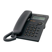
Identifies and explains the function of various buttons and indicators.
Explains the different display configurations and their meanings.
Guides on connecting the handset, line cord, and external devices.
Steps for removing the main cabinet cover of the unit.
General troubleshooting tips and component checks for common issues.
Diagnostic flowcharts for issues related to pulse dialing.
Troubleshooting steps for tone dialing issues experienced with the handset.
Procedure to diagnose and resolve issues with the unit not ringing.
Explanation of the circuit that detects and signals incoming calls.
Description of how the unit connects to and interacts with the telephone line.
Details on the operation and switching within the speakerphone system.
Explanation of how the system detects and processes Caller ID information.
Details the pin assignments and functional blocks of the IC903 CPU.
Overview of the LCD module's internal structure and connections.
Lists pin assignments for various connectors on the module.
Lists necessary tools and materials for IC replacement.
Step-by-step guide for safely removing flat package ICs.
Step-by-step guide for soldering and installing flat package ICs.
Illustrates the unit's components and lists their part numbers.
Illustrates the included accessories and how the product is packed.
Provides pinout and identification for various ICs, transistors, and diodes.
Lists replaceable parts for the main unit, including ICs and discrete components.
Lists specific components mounted on the main printed circuit board.
Explains symbols, notations, and safety areas used in schematics.
Detailed schematic of the primary electronic circuits within the unit.
Schematic illustrating the operational logic and user interface circuits.
Shows the placement of components on the main circuit board.
Illustrates the solder side layout of the main circuit board.
Shows the placement of components on the operation circuit board.
Illustrates the solder side layout of the operation circuit board.
| Type | Corded |
|---|---|
| Display | LCD |
| Speakerphone | Yes |
| Caller ID | Yes |
| Volume Control | Yes |
| Color | Black |
| Phonebook entries | 50 |
| Wall Mountable | Yes |
| Ringer Volume Control | Yes |
| Redial | Yes |
| Flash | Yes |
| Call Waiting | Yes |
| Handset Volume Control | Yes |
| Phonebook | Yes |
| Power Source | Phone line |