Do you have a question about the Panasonic KX-TS600MXW and is the answer not in the manual?
Details on recommended lead-free solder types and sizes for product servicing.
Instructions for installing and replacing batteries in the telephone unit.
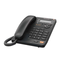
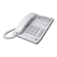
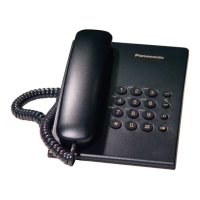
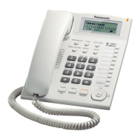
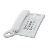
Identification and explanation of buttons and features on the telephone.
Explanation of various display messages and symbols on the telephone.
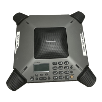
Guidance on connecting the handset, telephone line, and communication devices.
Procedure for setting and canceling the dial lock feature for security.
Common problems and their potential causes and remedies.
General tips and cures for common telephone symptoms.
Diagnostic flowchart for issues related to pulse dialing.
Diagnostic flowchart for tone dialing issues with the handset.
Diagnostic flowchart for troubleshooting no-ring issues.
Explanation of the circuit that detects bell signals.
Description of the circuit handling telephone line communication.
Overview of the main functional blocks within the telephone system.
Detailed circuit operation for the telephone line interface.
Circuit operation for sensing line status like busy or dial tone.
Function and operation of the circuit that initializes the microcomputer.
Explanation of the circuit that detects and processes Caller ID signals.
Block diagram and pin overview for the main CPU IC903.
Detailed pin data and functions for the IC903 CPU.
Block diagram and pin descriptions for the Ringer IC (IC1).
Block diagram and pin descriptions for the EEPROM IC802.
Detailed pin data and functions for the Speakerphone IC601.
Block diagram and pin configuration for the LCD module.
Table detailing the pin assignments for various connectors.
Required materials and tools for replacing flat package ICs.
Step-by-step guide for safely removing flat package ICs.
Step-by-step guide for correctly installing flat package ICs.
Procedure for performing bridge modifications on circuit boards.
List of replacement parts for the base unit of the telephone.
List of replacement parts for the operational printed circuit board.
List of accessories and packing materials included with the product.
Component layout diagram for the main circuit board.
Solder side layout diagram for the main circuit board.
Component layout diagram for the operation circuit board.
Solder side layout diagram for the operation circuit board.
| Type | Corded Phone |
|---|---|
| Color | White |
| Caller ID | Yes |
| Speakerphone | Yes |
| Phonebook | Yes |
| Redial | Yes |
| Ringer Volume Control | Yes |
| Wall Mountable | Yes |
| Call Waiting | Yes |
| Handset Volume Control | Yes |
| Display | LCD |
| Dialing Type | Tone |
| Phonebook Memory | 50 Names |