Do you have a question about the Panasonic KX-TSC11MXW and is the answer not in the manual?
Recommends specific lead-free solder types and sizes for service.
Details how to recognize if lead-free solder was used on PCBs.
Precautions for preventing malfunctions when handling sensitive electronic components.
Warning regarding battery replacement safety and disposal.
Step-by-step guide for inserting batteries into the unit.
Instructions for replacing depleted batteries and data retention.
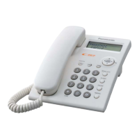
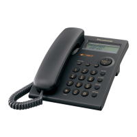
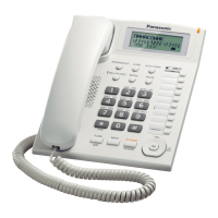
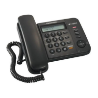
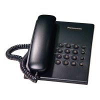
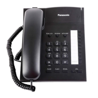
Identifies all buttons and indicators on the telephone unit.
Explains how to use the navigator key for menu navigation and selection.
Explains various display messages and icons shown on the unit.
Procedure to restore all settings to their original factory presets.
Instructions for connecting the handset and telephone line cord.
How to program the unit for Tone or Pulse dialing.
How to enable, disable, and manage the dial lock feature.
Steps to release or change the password for locked features.
How to program the unit to restrict dialing specific number prefixes.
Basic procedures for initiating and receiving phone calls.
How to redial the last number or browse the redial list.
Adjusting the earpiece volume during a call.
How to handle incoming calls when already on a call.
Using the FLASH button for PBX features and setting flash time.
Instructions for listening to voice mail messages.
Storing, editing, and dialing numbers from the phone book.
Using stored numbers sequentially for complex dialing sequences.
Modifying names and numbers stored in the phone book.
Removing unwanted entries from the phone book.
Quick checks and common fixes for various unit malfunctions.
Troubleshooting steps for problems with pulse dialing.
Troubleshooting steps for problems with DTMF tone dialing.
Diagnosing issues when the unit does not ring.
Step-by-step guide for disassembling the telephone unit.
Procedure to test the functionality of all keypad buttons.
High-level view of the telephone's internal functional blocks.
Explanation of the circuit that detects incoming ring signals.
How the unit connects and interacts with the telephone line.
The circuit responsible for CPU initialization upon power-up.
How the unit receives and decodes Caller ID information.
Detailed block diagram of the main CPU IC (IC502).
Detailed pin description and function for the main CPU (IC502).
Functional diagram of the ringer integrated circuit.
Explanation of the EEPROM's role in data storage.
Procedure for safely replacing surface-mount ICs.
Pinouts and identification for various ICs, transistors, and diodes.
Diagram showing the physical layout of internal parts and fasteners.
List of accessories and materials used for packaging the unit.
Identifies parts with Retention Time Limited (RTL) status.
List of components mounted on the main printed circuit board.
Part numbers for external and structural components.
Detailed list of resistors and capacitors with specifications.
Part numbers for inductors, connectors, and switches.
Detailed list of capacitors with part numbers and values.
Part numbers for included accessories and packaging.
Important notes and symbols used in the schematic diagrams.
Detailed electrical schematic of the telephone unit.
Labeled diagram showing component placement on the PCB.
Diagram showing component layout on the solder side of the PCB.
| Color | White |
|---|---|
| Display | LCD |
| Number of Ringtones | 10 |
| Speakerphone | Yes |
| Caller ID | Yes |
| Phonebook Capacity | 50 |
| Redial | Yes |
| Wall Mountable | Yes |
| Call Waiting | Yes |
| Intercom | No |
| Number of Handsets | 1 |
| Expandable | No |
| Answering Machine | No |