Start up Operation-1
Ex. 43/49DS630** series (Each models are different pin allocation but operation is same.)
P
Transformer P4
T7301 Q7402/05
24V/32V(*)
LD1
LD
L7813/14/
LD2
3,7
LCD Module
VLED1,2(*) Power
24V/
PFC Output 32V(*)
T7202
IC7201
DC/DC
IC7301
Q7804/01
(DC/DC)
LED 1,5
Drive
IC7800
6
3
P2
(light)
5
A02
For
LED
(Back
Light)
LCD Panel
T-CON
board
PNL12V
4
16V
Output Q7403
DC/DC
IC7503
BL_ON
11
1,2,3 16V
1
7 STB5V
9
TV_SUB_ON
12
POWER_ON
10
1,3,5
11
2
2
4
A19 1,2,3,4
F15V
STB5V
KEY3
A
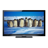
When the TV is plugged in, the power board outputs 5V for standby voltage.
POWER
Switch
When the power supply receives the TV_SUB_ON signal, it outputs 2 different voltages:
•16V to the A board on pins 1, 2, and 3 of connector P2.
•24/32V to the LED backlight board on pins 8,9 of connector P4.
After A board is ready to display, it outputs Backlight_on command to LD board.
26