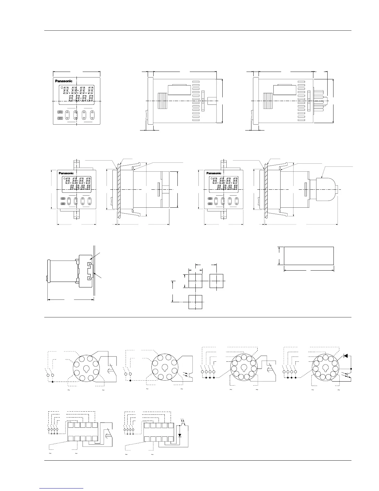
EasyManua.ls Logo

Panasonic LT4H/-L - Dimensions; LT4 H digital timer; Installation panel cut-out dimensions; Terminal layouts and Wiring diagrams

Panasonic LT4H/-L
16 pages
Print Icon
To Next Page IconTo Next Page
To Previous Page IconTo Previous Page
Loading...
Dimensions
• LT4H digital timer
(units: mm inch)
Tolerance: ±1.0 ±.039
Terminal layouts and Wiring diagrams
• 8-pin type
Relay output type Transistor output type
• Screw terminal type
• Dimensions for embedded installation (with adapter installed)
Dimensions for front panel installations
Installation panel cut-out dimensions
The standard panel cut-out dimensions are shown
below. Use the mounting frame (AT8-DA4) and rub-
ber gasket (ATC18002).
• For connected installations
Note) 1: The installation panel thickness should be between 1
and 5 mm .039 and .197 inch.
Note) 2: For connected installations, the waterproofing ability
between the unit and installation panel is lost.
LT4H
TIMER
RESET
LOCK
UP
hms
OP.
RST
LOCK
DOWN
48
1.890
5.5
.217
55.6
2.189
14.5
.571
7.5
.295
44.5
1.752
7.5
.295
5.5
.217
64.5
2.539
44.5
1.752
Screw terminal type
(Flush mount)
Screw terminal type Pin type
Pin type
(Flush mount/Surface mount)
LT4H
TIMER
UP
OP.
RST
LOCK
DOWN
LOCK
RESET
smh
Mounting frame
for flush mount
AT8-DA4 (supplied)
Panel
Rubber gasket
ATC18002 (supplied)
1
.039
11-pin type
(11p cap AT8-DP11
sold separately)
8-pin type
(8p cap AD8-RC
sold separately)
48
1.890
90
3.543
48
1.890
66
2.598
50
1.969
DIN rail terminal block
(8-pin type AT8-DF8K
sold separately)
(11-pin type AT8-DF11K
sold separately)
Device installation rail
AT8-DLA1
(sold separately)
95.5
(90.0)
3.760
(3.543)
( ) dimension is for 8-pin type.
80 min.
3.150
80 min.
3.150
45
+0.6
0
1.772
+.024
0
45
+0.6
0
1.772
+.024
0
A
A = (48 × n – 2.5)
+0.6
0
45
+0.6
0
1.772
+.024
0
8
5
1
7
6
2
3
4
Operating
voltage
+
N.O.
N.C.
Start
Reset
Operating
voltage
+
8
5
1
7
6
2
3
4
Start
Reset
• 11-pin type
Relay output type Transistor output type
Operating
voltage
+
N.O.
N.C.
3
5
4
2
1
11
10
9
8
7
6
Reset
Lock
Start
Stop
Operating
voltage
+
3
5
4
2
1
11
10
9
8
7
6
Reset
Lock
Start
Stop
Operating
voltage
+
54321
109876
N.O.
N.C.
Reset
Lock
Start
Stop
Operating
voltage
+
54321
109876
Reset
Lock
Start
Stop
LT4H/-L
Note) For connecting the output leads of the transistor output type, refer to
5) Transistor output on page 48.
All Rights Reserved © COPYRIGHT Matsushita Electric Works, Ltd.

Related product manuals