EasyManua.ls Logo

Panasonic LT4H/-L User Manual

Panasonic LT4H/-L
16 pages
To Next Page IconTo Next Page
Page #1 background imageLoading...
Page #1 background image
Features
1. Bright and Easy-to-Read Display
A brand new bright 2-color back light
LCD display. The easy-to-read screen in
any location makes checking and setting
procedures a cinch.
2. Simple Operation
Seesaw buttons make operating the unit
even easier than before.
3. Short Body of only 64.5 mm 2.539
inch (screw terminal type) or 70.1 mm
2.760 inch (pin type)
With a short body, it is easy to install in
even narrow control panels.
4. Conforms to IP66’s Weather
Resistant Standards
The water-proof panel keeps out water
and dirt for reliable operation even in
poor environments.
5. Screw terminal (M3.5) and Pin
Types are Both Standard Options
The two terminal types are standard
options to support either front panel
installation or embedded installation.
6. Changeable Panel Cover
Also offers a black panel cover to meet
your design considerations.
7. Compliant with UL, c-UL and CE.
48
1.890
48
1.890
64.5
2.539
Pin type Screw terminal type
Time range Operating mode Output Operating voltage Power down insurance Terminal type Part number
9.999 s (0.001 s~)
99.99 s (0.01 s~)
999.9 s (0.1 s~)
9999 s (1 s~)
99 min 59 s (1 s~)
999.9 min (0.1 min~)
99 h 59 min (1 min~)
999.9 h (0.1 h~)
Power ON delay (1)
Power ON delay (2)
Signal ON delay
Signal OFF delay
Pulse One-shot
Pulse ON-delay
Signal Flicker
Totalizing ON-delay
(8 modes)
Relay
(1 c)
Transistor
(1 a)
100 to 240 V AC
24 V AC
100 to 240 V AC
24 V AC
12 to 24 V DC
12 to 24 V DC
Available
11 pins
Screw terminal
11 pins
Screw terminal
11 pins
Screw terminal
11 pins
Screw terminal
LT4H-AC240V
8 pins LT4H8-AC240V
LT4H-AC240VS
LT4H-AC24V
8 pins LT4H8-AC24V
LT4H-AC24VS
LT4HT-AC240V
8 pins LT4HT8-AC240V
LT4HT-AC240VS
LT4HT-AC24V
8 pins LT4HT8-AC24V
LT4HT-AC24VS
11 pins
Screw terminal
11 pins
Screw terminal
LT4H-DC24V
8 pins LT4H8-DC24V
LT4H-DC24VS
LT4HT-DC24V
8 pins LT4HT8-DC24V
LT4HT-DC24VS
Product types
UL File No.: E122222
C-UL File No.: E122222
LT4H Timers
mm inch
* A rubber gasket (ATC18002) and a mounting frame (AT8-DA4) are included.
DIN 48 SIZE
DIGITAL TIMER
LT4H/-L
Timers
RoHS Directive compatibility information
http://www.nais-e.com/
All Rights Reserved © COPYRIGHT Matsushita Electric Works, Ltd.
Question and Answer IconNeed help?

Do you have a question about the Panasonic LT4H/-L and is the answer not in the manual?

Panasonic LT4H/-L Specifications

General IconGeneral
BrandPanasonic
ModelLT4H/-L
CategoryTimer
LanguageEnglish

Summary

Features

Bright and Easy-to-Read Display

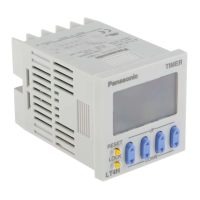
Highlights the dual-color backlight LCD for clear visibility.

Short Body

Describes the compact body for easy installation in narrow panels.

Conforms to IP66's Weather Resistant Standards

Ensures reliable operation in harsh environments due to water and dirt resistance.

Features (LT4H-L)

Economically priced

Offers excellent cost performance for market needs.

Inherits all of the characteristics of the LT4H digital timer

Includes seesaw switches and IP66 protection.

Part names

Front display section

Details the components and indicators on the timer's front display.

DIP switches

Illustrates the location and function of the DIP switches.

Specifications

Rating

Covers electrical ratings like operating voltage, power, and control capacity.

Time

Details time accuracy, temperature error, and voltage error specifications.

Applicable standard

Lists relevant safety standards like EN61812-1.

Dimensions

LT4H digital timer

Provides overall dimensions for the LT4H digital timer unit.

Installation panel cut-out dimensions

Specifies standard panel cut-out dimensions for installation.

Terminal layouts and Wiring diagrams

8-pin type

Shows terminal layout and wiring for the 8-pin type.

11-pin type

Shows terminal layout and wiring for the 11-pin type.

Screw terminal type

Shows terminal layout and wiring for the screw terminal type.

Setting the operation mode, time range, and time

Setting procedure 1) Setting the operation mode and time range

Explains setting the operation mode and time range using DIP switches.

Setting procedure 2) Setting the time

Details how to set the timer value using the front panel keys.

Changing the set time

Describes how to change the set time during operation.

Operation mode

Power on delay (1)

Describes Power ON delay (1) operation mode and time chart.

Power on delay (2)

Explains Power ON delay (2) operation mode and time chart.

Signal on delay

Details Signal ON delay operation mode and time chart.

Signal off delay

Describes Signal OFF delay operation mode and time chart.

Operation Modes Explained

Pulse One-shot

Explains Pulse One-shot operation mode and time chart.

Pulse On delay

Details Pulse ON delay operation mode and time chart.

Signal Flicker

Describes Signal Flicker operation mode and time chart.

Totalizing On delay

Explains Totalizing ON delay operation mode and time chart.

Remarks and notes

Provides important remarks and notes regarding operation modes.

Features (LT4H-W)

Wide time range

Covers a broad time range from 0.01 sec. to 9999 hours.

Short Body

Compact body design for easy installation in narrow panels.

Compliant with UL, c-UL and CE

Meets UL, c-UL, and CE compliance requirements.

Low Price

Offers unmatched cost performance at an affordable price.

Part names (LT4H-W)

T1/T2 Operation display

Describes the displays related to T1/T2 settings.

DIP switches

Illustrates the DIP switches for setting.

Specifications (LT4H-W)

Rating

Details electrical ratings for relay and transistor output types.

Electrical

Details breakdown voltage, insulation resistance, and reset time.

Applicable standard

Lists safety standards including EN61812-1.

Dimensions (LT4H-W)

LT4H-W digital timer

Provides overall dimensions for the LT4H-W timer.

Installation panel cut-out dimensions

Specifies standard panel cut-out dimensions.

Applicable standard (LT4H-W)

Safety standard

Lists safety standards and pollution/overvoltage categories.

EMC

Details EMC compliance and immunity standards.

Terminal layouts and Wiring diagrams (LT4H-W)

8-Pin type

Shows terminal layouts and wiring diagrams for the 8-pin type.

11-Pin type

Displays terminal layouts and wiring for the 11-pin type.

Screw terminal type

Presents terminal layouts and wiring for the screw terminal type.

Setting the operation mode and time range (LT4H-W)

Setting procedure 1) Setting the time range (Timer T1/Timer T2)

Explains setting time range using DIP switches for Timer T1 and T2.

Setting procedure 2) Setting the operation mode

Details how to set the operation mode using front panel keys.

Changing the set time

Provides guidelines for changing the set time during operation.

OPERATION MODE

PULSE A OFF-start/1 operation

Details the PULSE A OFF-start/1 operation mode and its time chart.

INTEGRATION A OFF-start/1 operation

Explains INTEGRATION A OFF-start/1 operation and its time chart.

PULSE B OFF-start/repeating operation

Describes PULSE B OFF-start/repeating operation and its time chart.

Remarks and notes

Provides important remarks and notes regarding operation modes.

PRECAUTIONS IN USING THE LT4H SERIES

1. Terminal wiring

Provides essential guidance for proper terminal wiring and connections.

2. Input connections

Explains precautions for input signal connections to avoid damage.

3. Input and output

Details signal input types and output considerations.

PRECAUTIONS IN USING THE LT4H SERIES

4. Operation of LT4H digital timer

Covers specific operating modes and their behavior.

5. Operation mode and time range setting

Explains how to set operation modes and time ranges.

6. Conditions of usage

Lists environmental and usage conditions to avoid.

7. Acquisition of CE marking

Details conditions for CE marking compliance.

PRECAUTIONS IN USING THE LT4H SERIES

6) Long periods of continuous operation

Advises on avoiding long continuous operation to prevent heat damage.

7. Acquisition of CE marking

Details conditions for CE marking compliance, including categories.

7. Self-diagnosis function

Explains how to interpret and handle self-diagnosis error displays.

Related product manuals