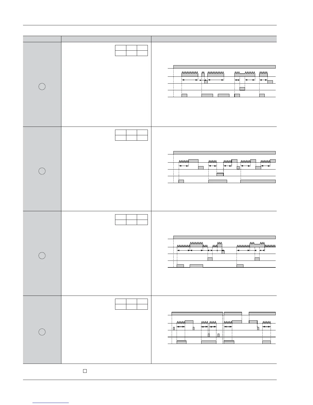
Operation type
Pulse One-shot
Explanation Time chart
• Set the operation mode
section of the DIP switches
(no.’s 1, 2, and 3) on the
side of the timer as shown.
• Clears elapsed time value at power ON.
• Time delay starts and output control ON at
start ON.
• Turns output control OFF and clears elapsed
time value at time-up.
• Ignores start input during time delay.
• Stops delay time operation at stop ON.
Restarts delay time operation at stop OFF.
• In order to have the time delay start at power
ON or reset at power OFF, short out the start
input beforehand.
D
Pulse On delay
E
Signal Flicker
F
Totalizing On delay
G
123
ON ON OFF
• Set the operation mode
section of the DIP switches
(no.’s 1, 2, and 3) on the
side of the timer as shown.
• Clears elapsed time value at power ON.
• Time delay starts at start ON.
• Ignores start input during time delay.
• Stops delay time operation at stop ON.
Restarts delay time operation at stop OFF.
• In order to have the time delay start at power
ON or reset at power OFF, short out the start
input beforehand.
123
OFF OFF ON
• Set the operation mode
section of the DIP switches
(no.’s 1, 2, and 3) on the
side of the timer as shown.
• Clears elapsed time value at power ON.
• Time delay starts at start ON.
• Ignores start input during time delay.
• Output control reverses, elapsed time value
clears, and timer delay starts at timer comple-
tion.
• Stops delay time operation at stop ON.
Restarts delay time operation at stop OFF.
• In order to have the time delay start at power
ON or reset at power OFF, short out the start
input beforehand.
123
ON OFF ON
• Set the operation mode
section of the DIP switches
(no.’s 1, 2, and 3) on the
side of the timer as shown.
• Elapsed time value does not clear at power
ON. (power outage countermeasure function)
• The output remains ON even after the power
is off and restarted.
• Stops delay time operation at stop ON.
Restarts delay time operation at stop OFF.
123
OFF ON ON
LT4H/-L
Notes: 1) Each signal input (start, reset, stop, and lock) is applied by shorting their input terminal to the common terminal (terminal Q for the 8-pin type, terminal E for
the 11-pin type, and terminal for the screw terminal type).
2) The 8-pin type does not have a stop input or lock input.
6
T: Set time t1, t2, t3, ta<T