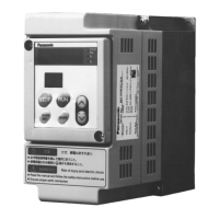
This document describes the Panasonic Low-Noise Inverter M1S Series, designed for speed control of 3-phase induction motors.
Function Description
The M1S Series inverter provides precise speed control for 3-phase induction motors. It integrates various functions for motor operation, protection, and system integration. Key functionalities include:
- Motor Speed Control: Regulates the output frequency to control the motor's rotational speed.
- Direction Control: Allows for forward and reverse operation of the motor.
- Frequency Setting: Offers multiple methods for setting the operating frequency, including external volume, control input terminals, and operation panel.
- Monitoring: Displays critical operational parameters such as output frequency, set frequency, output current, converter voltage, and error codes.
- Protective Functions: Incorporates various safety features to protect the inverter, motor, and connected equipment from damage due to overcurrent, overvoltage, undervoltage, overheating, and other abnormal conditions.
- Regenerative Brake Control: For models with a built-in regenerative brake circuit, it enhances the inverter's capacity to handle regenerative energy from the motor.
- Communication Functions: Certain models (indicated by interface specs C and D) offer communication capabilities for integration into larger control systems.
Important Technical Specifications
The M1S Series offers a range of models with varying power ratings and voltage classes.
General Specifications:
- Input Voltage: Available in Single-phase 100V, Single-phase 200V, and 3-phase 200V classes.
- Output Voltage: 3-phase AC 200~230V (for 200V class models).
- Output Frequency Range: 0~400Hz.
- Motor Capacity: Ranges from 0.1 kW to 0.75 kW.
- Protection Structure: IP40 (Built-in the panel).
- Ambient Temperature: -10°C to 50°C (Single-phase input: -10°C to 40°C). Must not freeze.
- Ambient Humidity: Max. 90%RH (Must be no condensation).
- Storage Temperature: -20°C to 65°C (Must not freeze).
- Storage Humidity: Max. 90%RH (Must be no condensation).
- Vibration: Max. 5.9 m/s² (10 ~ 60Hz).
- Elevation: Max. 1000 m.
Model-Specific Example (M1S083CSA):
- Power: 750W
- Input: 3-phase AC 200~230V, 50/60Hz, 4.6A
- Output: 3-phase AC 200~230V, 0~400Hz, 4.0A
- Interface Specs: Without communication function/standard type (NPN logic).
- Operation Panel Specs: Without volume (standard).
- Regenerative Brake Specs: Without regenerative brake circuit.
Wiring Terminal Specifications:
- Main Circuit Terminals (R,S,T / L1,L2,L3; U,V,W / T1,T2,T3): M3.5 screw size, 0.8~1.0 N·m tightening torque.
- GND Terminal (E): M4 screw size, 1.0~0.2 N·m tightening torque.
- Reactor/Regenerative Resistor Terminals (PD, P, PB): M2.5 screw size, 0.3~0.5 N·m tightening torque.
- Control Terminals (5V, G, FIN1, FOUT, I1-I5, 01, C1, NC, NO, C2): M2 screw size, 0.25~0.3 N·m tightening torque.
Usage Features
The inverter is designed for user-friendly operation and flexible system integration.
- Operation Panel: Features a 5-digit LED for displaying parameters and a 2-digit LED for parameter numbers and rotation direction. Dedicated buttons (STOP, RUN, DATA SET, MODE, UP/DOWN arrows) facilitate easy navigation and setting adjustments.
- Multiple Operation Modes: Supports various operation command selections, allowing control from the operation panel, external terminal block, or a combination of both for frequency and run commands.
- Parameter Setting: Comprehensive parameter settings allow customization of inverter behavior, including frequency command source, run command source, acceleration/deceleration times, motor characteristics, and protective function thresholds.
- Test Operation: A clear procedure is provided for initial test runs, ensuring safe and correct setup before full operation. This includes checking wiring, input power, and motor behavior.
- External Control Inputs: Offers terminals for forward/stop, reverse/stop, frequency setting selection (2-speed, 4-speed, 8-speed operation), and trip reset.
- Output Signals: Provides open-collector output (01, C1) for trip signals or other selected functions, and relay output (NC, NO, C2) for general status indications.
- Frequency Meter Output: A dedicated terminal (FOUT) provides a voltage proportional to the output frequency, allowing connection to an external DC ammeter for monitoring.
Maintenance Features
Proper maintenance is crucial for the inverter's longevity and safe operation.
- Pre-operation Inspections: Before initial startup, users are instructed to verify correct wiring, input power compliance, absence of short circuits, and tightness of screws/terminals.
- Safety Precautions: Emphasizes critical safety measures during installation, wiring, operation, and maintenance, including:
- Disconnecting power before handling wiring or performing inspections.
- Waiting at least 5 minutes after power-off before touching internal components due to residual high voltage.
- Ensuring proper grounding of the GND terminal.
- Using insulated tools and removing metallic objects during maintenance.
- Never modifying the inverter.
- Ensuring the case and cover are mounted before turning on power.
- Avoiding contact with hot parts like the radiator and regenerative resistor.
- Installation Guidelines: Provides detailed instructions for proper installation location (indoors, away from combustibles, corrosive gases, dust, and vibration) and mounting direction with specified clearances for effective cooling.
- Peripheral Equipment Selection: Recommends specific no-fuse breakers, magnetic contactors, thermal relays, and wire sizes based on the inverter model to ensure system compatibility and protection.
- Control Circuit Wiring: Advises on proper wire stripping length, wire diameter for terminals, and the use of shielded wires for control circuits to prevent interference.
- Troubleshooting: (Mentioned in the table of contents) The manual likely includes a section dedicated to troubleshooting common issues, although the details are not provided in the extracted pages.
- Servicing: (Mentioned in the table of contents) Indicates that information on servicing is available, possibly on the back cover or a dedicated section.
- Disposal: Instructions to treat the inverter as industrial waste when disposing of it.