S
Sean HamiltonAug 1, 2025
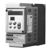
What to do if Panasonic VF0 400V class Inverter motor doesn't rotate and fault display is lit?
- MMr. Ethan DuffyAug 1, 2025
If the motor does not rotate and the fault display is lit, it indicates an inverter malfunction. Contact Matsushita for assistance.