EasyManua.ls Logo

Panasonic NE-1027 - NE-1037 Control Panel Overview; Digital Display and Indicator Locations; Control Panel Pads Explained; Initial Setup and Basic Operation (NE-1037)

Panasonic NE-1027
23 pages
To Next Page IconTo Next Page
To Previous Page IconTo Previous Page
Loading...
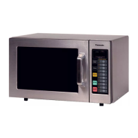
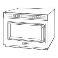
Outline Diagram NE-1037
- 9 -
NE-1037
X
2
x2
12 3
1
2
3
4
5
0
9
8
7
6
(1) Digital Display Window (see below)
(2) Power Level Pad
(3) Program Pad
(4) Double Quantity (x2) Pad
(5) Start Pad
(6) Stop/Reset Pad
(7) Memory Pads
(8) Control Panel
(9) Door Safety Lock System
(10) Oven Window
(11) Oven Lamp
X
2
x2
1
1
2
3
4
5
0
9
8
7
6
3
Digital Display Window Indicator Locations
x2
12
3
E
D
AB
C
A - Program Change Indicator
B - Double Quantity (x2) Heating Indicator
C - Memory Pad Number and Heating Time
Display (min. sec.)
D - Stage Heating Indicator
E - Power Level Indicator
1000 W
500 W
340 W (Defrost)
(1)
(2)
(3)
(4)
(5)
(6)
(7)
(9)
(8)
(11)
(10)

Other manuals for Panasonic NE-1027

Related product manuals