Do you have a question about the Panasonic NE-1757CR and is the answer not in the manual?
Step-by-step guide for operating the oven in manual single-stage heating mode.
Procedure for operating the oven in manual two or three-stage heating modes.
Procedure for replacing the upper and lower magnetron components in the oven.
Procedure for testing the high voltage transformer's continuity and resistance.
How to test the high voltage capacitor for continuity and shorts.
Testing methods for the magnetron's filament and case continuity.
Procedure for testing diodes using an ohmmeter for front-to-back resistance.
Checking continuity of membrane switch contacts on the keyboard.
Testing the protector diode for continuity in both directions.
Steps for mounting safety and short switches to the door hook assembly.
Procedure to measure microwave output power using a water load test.
Lists necessary equipment for measuring microwave leakage.
Guidelines for recording leakage readings and reporting excessive levels.
Recommendation for annual calibration of radiation monitoring equipment.
| Control Type | Electronic |
|---|---|
| Turntable | Yes |
| Weight | 36 lbs |
| Frequency | 2450 MHz |
| Voltage | 120 V |
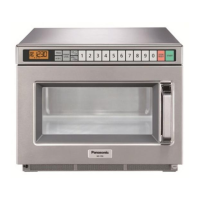
| Finish | Stainless Steel |
| Type | Commercial Microwave Oven |
| Category | Microwave Oven |
| Cooking Modes | Microwave |
| Exterior Dimensions (W x D x H) | 21 5/8" x 19 1/4" x 12 1/4" |