Do you have a question about the Panasonic NN-CS596S SPG and is the answer not in the manual?
Schematic diagram for BPQ and EPG models of the microwave oven.
Schematic diagram for WPG and SPG models of the microwave oven.
Explanation of how variable power cooking is controlled via PWM signals.
Details of the high voltage inverter power supply circuit operation and components.
How the digital programmer controls convection and grill heating.
Details on the steam function, including water supply and operation.
Importance of proper grounding before commencing any repair work.
Critical safety warnings related to high voltage and high temperatures in the inverter circuit.
Steps to ensure the unit is safe and functioning correctly after repair.
Step-by-step guide for disassembling and replacing the magnetron component.
Procedure for removing the DPC boards, membrane keyboard, and power relay.
Detailed procedure for removing and replacing the High Voltage Inverter unit.
Detailed steps for removing convection motor and heater components.
Testing procedures for primary latch switch, door switch, and power relay B.
Methods for testing the magnetron for open filament or short circuits.
Guidelines for testing the High Voltage Inverter power supply unit.
Adjusting latch switches and short switch for proper door closure and interlock function.
Procedure for measuring the microwave output power using a water load test.
How to access and interpret the oven's self-diagnostic error codes.
Troubleshooting steps for when the oven stops mid-cooking cycle.
Specific troubleshooting for inverter and magnetron failures indicated by error codes H95-H99.
Visual breakdown of the oven components with reference numbers.
Comprehensive list of all replaceable parts with part numbers and descriptions.
Exploded view and parts list for the oven door components.
Detailed schematic diagram of the digital programmer circuit.
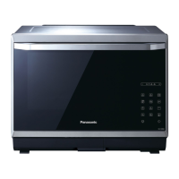
| Brand | Panasonic |
|---|---|
| Model | NN-CS596S SPG |
| Category | Microwave Oven |
| Language | English |