
S
Sharon HarrisAug 15, 2025
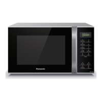
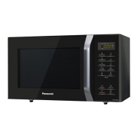
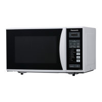
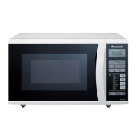
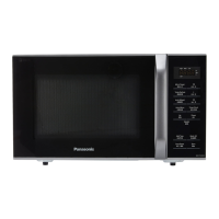
Why my Panasonic Microwave Oven does not work?
- SsotostevenAug 15, 2025
If your Panasonic Microwave Oven isn't working, it could be due to several reasons. Avoid overloading the outlet by using too many appliances at once, and make sure the microwave plug is inserted securely. Also, ensure that the AC input voltage is adequate for the microwave's operation.