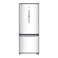
Do you have a question about the Panasonic NR-BV368 and is the answer not in the manual?
General warnings for safe operation and repair of the refrigerator. Emphasizes unplugging the unit and using authentic parts.
Specific cautions regarding hot parts, refrigerant handling, sharp edges, and brazing procedures to prevent injury.
Step-by-step guide on how to disassemble the door control assembly for the X series refrigerator, including component removal.
Instructions for disassembling the PC door, including removing the hinge top and the door itself, with visual aids.
Procedure for removing the LED light assembly from the refrigerator, involving loosening hooks and disconnecting the PCB.
Steps to remove the cover duct PC assembly, involving opening a screw cover and unscrewing the main component.
Guide to removing the Barrier PF assembly, involving taking out trays, unscrewing, and pulling out the unit.
Procedure to remove the cover dumper PC assembly by unscrewing and disconnecting sensors.
Steps to remove the fan motor assembly, including detaching the connector and carefully pulling out the motor.
Instructions for removing the FC (likely Freezer Compartment) by unscrewing the hinge center.
Steps to remove the cover coil assembly, involving pushing hooks and separating front and back covers.
Procedure for disassembling defrost heater, defrost sensor, and temperature fuse, involving wire disconnection and tube cutting.
Instructions for removing the motor protector, including taking out the pan water EVA and the cover protector.
Exploded view diagram illustrating the body components of the refrigerator, with numbered parts for identification.
Exploded views of the machine room assembly and door assemblies for different models (XS, QS) and series (BV288, BV328, BV368).
Illustrates the packing process and materials for the refrigerator, showing front views of different packing steps.
A detailed list of replacement parts for various models, including part numbers, descriptions, and quantities for different regions.
| Width | 600 mm |
|---|---|
| Depth | 650 mm |
| Cooling System | Direct Cool |
| Color | Silver |
| Warranty | 1 Year |