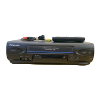
Do you have a question about the Panasonic Omnivision VHS PV-V402 and is the answer not in the manual?
Critical components for safety are marked; use specified parts to prevent hazards.
Procedures for cold and hot checks to ensure safety against electrical shock hazards.
Simplified self-diagnostic system uses fault codes for cause identification.
Accessing usage screen, service mode, and tracking center for diagnostics.
Notes for replacing EEPROM IC and Main CBA, requiring specific adjustments.
Details and cautions for operating the VCR in specific service positions.
Caution for hot circuits; procedure to enter service mode for mechanism checks.
Methods for loading/unloading mechanism and installing front panel assembly safely.
Step-by-step guide to safely remove a jammed tape from the VCR.
Procedures for resetting memory functions and confirming auto clock set feature.
Use of isolation transformers and handling of ESD-sensitive devices.
Marks used to distinguish between different VCR models in the manual.
Detailed instructions for disassembling and reassembling the VCR's cabinet section.
Procedures for disassembling and reassembling the VCR's internal mechanism.
Procedures for disassembling and reassembling the cassette up assembly unit.
Lists necessary tools and fixtures required for VCR servicing and adjustments.
Steps for mechanical adjustments including cylinder cleaning and tape tension.
Procedure to adjust back tension for smooth tape running and proper contact with heads.
Adjustments to ensure tape interchangeability, requires tracking center mode.
Adjusts RF envelope flatness for satisfactory picture and precise tracking.
Confirms tape runs smoothly, proper audio signal pickup, prevents tape damage.
Ensures tape runs properly along the control head for servo operation.
Adjusts audio control head position/height for proper tape track alignment.
Adjusts horizontal position of the audio control head for maximum envelope.
Procedures for electrical adjustments using electronic technology and remote control.
Determines video head switching point during playback for optimal tracking.
Identifies key test points and control locations on the Main C.B.A.
Notes regarding schematic diagrams and circuit board layouts.
Main schematic diagrams illustrating the VCR's circuitry.
Shows interconnections between major units like Main CBA, heads, tuners, etc.
Overall block diagram illustrating the VCR's main functional blocks and interconnections.
Exploded view of the mechanism's top section, showing parts and their assembly.
Exploded view of the mechanism's bottom section, detailing parts and lubrication points.
Exploded view of the cassette up compartment section.
Exploded view of chassis frame and casing parts.
Exploded view of packing parts and accessories included with the unit.
Important notes before replacing parts, including using original parts and safety precautions.
Notes specific to mechanical part replacements, including tape interchangeability adjustment.
Notes regarding electrical part replacements, including resistor values and abbreviations.
| Brand | Panasonic |
|---|---|
| Model | PV-V402 |
| Type | VCR |
| Tape Format | VHS |
| Playback Formats | VHS |
| Recording Formats | VHS |
| Tuner | NTSC |
| Remote Control | Yes |
| On-Screen Display | Yes |
| Inputs | Composite Video, Audio |
| Outputs | Composite Video, Audio |