1-13
CRT C.B.A.
Clamper
Degaussing Coil Connector
Clamper
P354
Note:
No lead wires or flat cables should touch
any heating parts or the Heat Sink Plate of
IC451, IC801, or Q551.
(Model : A, B, C, D, E) (Model : F, G, H)
(Model : I)
TV Main
C.B.A.
VCR Main
C.B.A.
CRT C.B.A.
Clamper
Deflection
Yoke
Connector
P1002
P4591
Flyback
Transformer
Degaussing Coil Connector
Clamper
Clamper
Clamper
Clamper
Frame
Anode Cap
Deflection Yoke
P354
Degaussing Coil
Grounding Wire
PK3
PK2
PK1
Clamper
45°
+
-
Red
White
Speaker-R
TV Main
C.B.A.
VCR Main
C.B.A.
Deflection
Yoke
Connector
P1002
P4591
Flyback
Transformer
Clamper
Clamper
Clamper
Frame
Anode Cap
Deflection Yoke
Degaussing Coil
Grounding Wire
PK3
PK2
PK1
Clamper
45°
+
-
Red
White
Speaker-R
TV Main
C.B.A.
VCR Main
C.B.A.
Deflection
Yoke
Connector
P1002
P4592
P4605
P4602
P4301
P4604
Flyback
Transformer
Clamper
Clamper
Clamper
Frame
TV Stereo C.B.A.
Stereo Amp C.B.A.
Anode Cap
Deflection Yoke
Degaussing Coil
Grounding Wire
PK3
PK2
PK1
Clamper
45°
+
-
Red
White
Red
White
Speaker -R Speaker -L
+
-
P4601
CRT C.B.A.
Clamper
Degaussing Coil Connector
Clamper
P354
(Model: G, H) (Model: F)
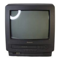
Wire and Lead position Diagram
After servicing, make sure that all wires and leads are placed
in their original position. It is important for the best operation of
the unit.
Fig. 6
 Loading...