EasyManua.ls Logo

Panasonic PV-M1327

Panasonic PV-M1327
143 pages
To Next Page IconTo Next Page
Loading...
©1996 Matsushita-Kotobuki Electronics Industries LTD.
All rights reserved. Unauthorized copying and distribution
is a violation of law.
Combination-VCR
ORDER NO. MKS9701M321
B3, B6
P
PV-M1327
P
PV-M1347
P
PV-M1357W
Q
VV1307
Q
VV1317W
P
PV-M2037
P
PV-M2047
Q
VV2007
Q
VV2017W
R
®
Weight
SP: 1
-
5/16 i.p.s (33.35 mm/sec), LP: 21/32 i.p.s (16.67 mm/sec),
SLP: 7/16 i.p.s (11.12 mm/sec)
Record/Playback Time: 8 Hrs with 160 min. type tape used in SLP mode
FF/REW Time: Less than 3 min. (120 min. type tape)
Tape width 1/2" (12.7 mm) high density tape
87.5 ~ 108.1 MHz
-- -
13 inch measured diagonal 90° deflection
---
20 inch measured diagonal 90° deflection
---
Source: 120V AC ± 10%, 60 Hz ± 0.5%
Consumption: Approx. 69 watts (power on), Approx. 6 watts (power off)
---
Approx. 110 watts (power on), Approx. 6 watts (power off)
---
EIA Standard (525 lines, 60 fields) NTSC Color Signal
41°F(5°C) ~ 104°F(40°C) (Temperature)
10% ~ 75% (Humidity)
15-3/16"(386mm) (W) X 15-7/8"(402.5mm) (H) X 16-11/16"(424mm) (D)
- ---
15-3/16"(386mm) (W) X 15-3/16"(385mm) (H) X 16-11/16"(424mm) (D)
- ----
20-3/10"(515mm) (W) X 19-4/5"(503mm) (H) X 19-1/10"(484mm) (D)
--- -
20-3/10"(515mm) (W) X 19-4/5"(505mm) (H) X 19-1/10"(484mm) (D)
---- -
27.4 lbs. (12.4 kg)
- ---
26.0 lbs. (11.8 kg)
- ----
49.95 lbs. (22.67 kg)
--- --
50.12 lbs. (22.75 kg)
-----
50.67 lbs. (23 kg)
---- -
ITEM SPECIFICATION
123456
Head: 2 rotary heads helical scanning system
- -
4 rotary heads helical scanning system
-- --
Input Level: VIDEO IN Jack (Phono type) 1.0 Vp-p 75 unbalanced
Signal-to-Noise Ratio: SP: more than 43 dB
LP/SLP: more than 41 dB
Horizontal Resolution: Color/Monochrome: more than 230 lines
Head: Normal Mono: 1 stationary head
Input Level: AUDIO IN Jack (Phono type) -10 dBv 50k unbalanced
Frequency Response: Normal Mono: SP: 100 Hz ~ 8 kHz
LP: 100 Hz ~ 6 kHz
SLP: 100 Hz ~ 5 kHz
Signal-to-Noise Ratio: Normal Mono: SP: more than 42 dB
LP/SLP: more than 40 dB
Wow and Flutter: Normal Mono: SP Less than 0.2% WRMS
LP: Less than 0.3% WRMS
SLP: Less than 0.4% WRMS
Broadcast Channels: VHF 2 ~ 13, UHF 14 ~ 69
CATV Channels: Midband A through I (14 ~ 22)
Superband J through W (23 ~ 36)
Hyperband AA ~ EEE (37 ~ 64)
Lowband A
-
5 ~ A
-
1 (95 ~ 99)
Special CATV channel 5A (01)
Ultraband 65 ~ 94, 100 ~ 125
ITEM SPECIFICATION
123456
SPECIFICATIONS
Video
Audio
VCR
Tuner
Tape
Speed
Tape
Format
VCR
Picture
Tube
DISPLAY
Power
Television
System
Operating
Condition
Dimension
GENERAL
Weight and dimensions shown are approximate.
Specifications are subject to change without notice.
1. PV-M1327
2. VV1307/VV1317W
3. PV-M1347/PV-M1357W
4. PV-M2037
5. VV2007/VV2017W
6. PV-M2047
FM Radio
Band
Renge
Question and Answer IconNeed help?

Do you have a question about the Panasonic PV-M1327 and is the answer not in the manual?
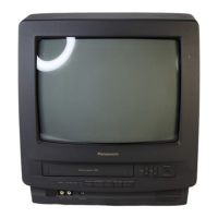
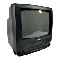
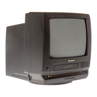
Panasonic PV-M1327 Specifications

General IconGeneral
BrandPanasonic
ModelPV-M1327
CategoryTV VCR Combo
LanguageEnglish

Summary

Safety Precautions

General Safety Guidelines

Important safety notices and general guidelines for servicing.

Leakage Current Checks

Procedures for performing cold and hot leakage current checks.

X-Radiation Warning

Warning regarding X-radiation sources and precautions.

Horizontal Oscillator Disable Circuit

Circuit Test, Repair, and Explanation

Procedure to test, repair, and explain the horizontal oscillator disable circuit.

Operation Guide

Control Layouts

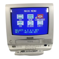
Diagrams of remote control and front panel controls and indicators.

One Time Setup Procedures

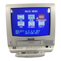
Initial setup for language, channels, clock, and channel replacement.

Picture Adjustment

Picture Settings Adjustment

Steps to adjust picture settings like brightness, contrast, color, and tint.

Closed Caption System

Closed Caption Configuration

Details on selecting closed caption modes and configuring the display screen.

FM Radio Operation

FM Radio Functions and Setup

Using FM radio features, memorizing stations, and selecting audio modes.

Tape Playback Operations

Playback Functions and Effects

Procedures for playback, scene search, special effects, and tracking control.

Tape Recording Procedures

Standard Recording

Basic instructions for recording directly onto a tape.

Timer Recording Management

Setting up, managing, canceling, and reviewing timer recordings.

Special VCR Features

VCR Lock and Warning Beeper

Explanation of the VCR lock feature and the warning beeper function.

Broadcast and Stereo System Setup

Broadcast Reception and Cable Box

Instructions for receiving broadcasts and configuring cable box connections.

TV Audio Mode Selection

How to select audio modes when viewing TV programs.

VCR Plus+ Setup

VCR Plus+ Configuration

Steps for VCR Plus+ setup and channel preparation.

Service Notes and Troubleshooting

Simplified Fault Finding Data

Information on fault finding, code positions, and service modes.

VCR Operational Modes

Procedures for service mode, auto tracking defeat, and memory reset.

Service Positions

Basic Service Positions

Describes two basic service positions without extension cables.

Service Position with Extension Cable Kit

Extension Cable Connection Procedures

Steps for connecting extension cables for service positioning.

How to Remove a Jammed Tape

Manual Tape Removal Methods

Step-by-step procedures for manually removing jammed tapes.

Electrical Method for Mechanism Movement

Mechanism Movement Procedures

Electrical procedures for moving the mechanism, including cautions.

Wire and Lead Position Diagram

Wire Routing Guidelines

Diagrams showing correct wire and lead placement after servicing.

Special Notes and Component Handling

Cylinder Rotation and Chassis Screws

Notes on cylinder behavior after stopping and identification of chassis screws.

ESD Sensitive Device Handling

Techniques for handling electrostatically sensitive devices and replacing chip components.

Service Mode and Special Functions

Service Mode Operations

Procedures for service mode, auto tracking defeat, and memory reset.

Component Information

Reading Component Identification

Guides on reading identification marks and values of chip components.

Disassembly Procedures - Cabinet

Disassembly Flowchart

Flowchart detailing the order of cabinet disassembly.

Swivel Unit Disassembly

Procedure for disassembling the swivel unit on specific models.

DisassemblyAssembly Procedures - Mechanism

Mechanism Disassembly Chart

Chart outlining the step-by-step disassembly of mechanism parts.

Adjustment Procedures and Service Tools

Service Fixtures and Tools

List and images of required tools for adjustments.

Mechanical Adjustments

Upper Cylinder Unit Cleaning

Procedure for cleaning the upper cylinder unit's video heads.

Tension Post Adjustment

Procedure for adjusting tape tension post for stability.

Back Tension Confirmation

Back Tension Measurement Procedure

Procedure to fine-tune back tension for smooth tape running.

Reel Table and FG Head Adjustments

Reel Table Height Adjustment

Procedure to align reel table height for proper tape path.

FG Head Gap Adjustment

Procedure to adjust FG head gap for proper servo operation.

Tape Path Alignment

P2 and P3 Post Height Adjustment

Preliminary adjustment of P2 and P3 posts for tape alignment.

Tape Interchangeability Adjustment

Envelope Output AdjustmentConfirmation

Final adjustment of envelope output for picture quality and tracking.

AC Head Adjustments

AC Head Tilt Confirmation

Confirming tape runs smoothly and checking for proper audio/control signal pickup.

AC Head Height Confirmation

Confirming tape runs properly along the control head.

AC Head Azimuth Adjustment

Adjusting A/C head position and height for proper tape track alignment.

AC Head Horizontal Position Adjustment

Horizontal Position Adjustment Procedure

Adjusting A/C head horizontal position for maximum envelope output.

Electrical Adjustment Procedures

Test Equipment for Adjustments

List and images of required tools for adjustments.

EVR Adjustment with Remote Control

Using remote control for electronic adjustments via on-screen display.

PG Shifter Adjustment

PG Shifter Adjustment Procedure

Adjusting video head switching point for playback.

Signal Separation and Sub Contrast

Separation Adjustment

Procedure to separate L and R channels of stereo signals.

Sub Contrast Adjustment

Setting the optimum sub contrast level for picture darkness/lightness.

FM VCO Adjustment

FM VCO Adjustment Procedure

Setting the VCO free run frequency for stereophony.

Picture Quality Adjustments

Focus, Screen, Cut Off, Drive Adjustments

Adjusting focus, screen, cut off, and drive for optimal picture quality.

Sub Color and Sub Tint Adjustment

Setting standard color phase by adjusting sub color and sub tint.

Purity Adjustment

Purity Adjustment Procedure

Setting uniform white over the screen and adjusting convergence magnet rings.

Convergence Adjustments

Static Central Convergence Adjustment

Setting uniform convergence across the screen.

Dynamic Convergence Adjustment

Setting uniform convergence at the sides of the CRT.

Picture Size and Position Adjustment

Vertical and Horizontal Position Adjustment

Setting standard vertical and horizontal picture size and position.

White Balance and Brightness Adjustment

White Balance Adjustment

Setting the standard white level for each color temperature.

Sub Brightness Adjustment

Setting the optimum brightness level for the picture.

Test Points and Control Locations

Main C.B.A. Test Points

Diagram showing test points and controls on the Main C.B.A.

CRT and TV Stereo C.B.A. Test Points

Diagram showing test points on CRT and TV Stereo C.B.A.

Schematic Diagram and Circuit Board Layout Notes

Notes on Using Schematics

Important notes regarding replacement parts, test points, and schematic interpretation.

Junction Schematic Diagram

Junction Schematic Diagram Details

Schematic diagram for the junction unit.

Stereo Amp Schematic Diagram

Stereo Amp Schematic Details

Schematic diagram for the stereo amplifier unit.

Main I Schematic Diagram

Main I Schematic Details

Schematic diagram for Main I (Power Supply/System Control/Servo).

Main II Schematic Diagram

Main II Schematic Details

Schematic diagram for Main II (Signal Process/OSD/Audio Amp).

Main III Schematic Diagram

Main III Schematic Details

Schematic diagram for Main III (TV Y/C Process).

Main IV Schematic Diagram

Main IV Schematic Details

Schematic diagram for Main IV (Power Supply).

TV Stereo Schematic Diagram

TV Stereo Schematic Details

Schematic diagram for the TV Stereo unit.

TV MainCRT Schematic Diagram

TV MainCRT Schematic Details

Schematic diagram for the TV Main and CRT units.

Circuit Board Layout - Head Amp C.B.A.

Head Amp C.B.A. Component Locations

Layout of components on the Head Amp C.B.A. for various models.

Circuit Board Layout - TV Stereo Amp & Junction C.B.A.

TV Stereo Amp C.B.A. Component Locations

Layout of components on the TV Stereo Amp C.B.A.

Junction C.B.A. Component Locations

Layout of components on the Junction C.B.A.

Circuit Board Layout - Main C.B.A.

Main C.B.A. Component Locations

Layout of components on the Main C.B.A. (Power Supply/Signal Process/OSD/Audio Amp).

Circuit Board Layout - TV Main C.B.A.

TV Main C.B.A. Component Locations

Layout of components on the TV Main C.B.A.

CRT C.B.A. Layout

CRT C.B.A. Component Locations

Layout of components on the CRT C.B.A.

Signal Waveform Diagrams

Waveforms for Main C.B.A.

Oscilloscope waveforms for various test points on the Main C.B.A.

Waveforms for Head Amp C.B.A.

Oscilloscope waveforms for Head Amp C.B.A. test points.

Power Supply Block Diagram

Power Supply Block Diagram Details

Block diagram of the power supply section.

Video Signal Path Block Diagram

Video Signal Path Diagram Details

Block diagram illustrating the video signal path.

Audio Signal Path Block Diagram

Audio Signal Path Diagram Details

Block diagram illustrating the audio signal path.

System Control Block Diagram

System Control Diagram Details

Block diagram of the system control section.

Servo Block Diagram

Servo Diagram Details

Block diagram of the servo control system.

TV YC ProcessOSDCCVTV Main Block Diagram

TV YC ProcessOSDCCVTV Main Diagram Details

Block diagram for TV Y/C processing, OSD, CCV, and TV Main functions.

Troubleshooting Hints - Power Supply Section

Power Supply Troubleshooting Flowchart

Flowchart for diagnosing power supply issues.

Troubleshooting - Video Section

Video Recording Troubleshooting

Flowchart for diagnosing video recording problems.

Troubleshooting - Video Section

Video Playback Troubleshooting

Flowchart for diagnosing video playback problems.

Exploded Views - Mechanism (Top) Section

Mechanism (Top) Parts Identification

Exploded view of the mechanism's top section with parts identification.

Exploded Views - Mechanism (Bottom) Section

Mechanism (Bottom) Parts Identification

Exploded view of the mechanism's bottom section with parts identification.

Exploded Views - Cassette Up Compartment Section

Cassette Up Compartment Parts Identification

Exploded view of the cassette up compartment with parts identification.

Exploded Views - Chassis Frame Section (1)

Chassis Frame (1) Parts Identification

Exploded view of the chassis frame (part 1) with parts identification.

Exploded Views - Chassis Frame Section (2)

Chassis Frame (2) Parts Identification

Exploded view of the chassis frame (part 2) with parts identification.

Exploded Views - Packing Parts and Accessories (A-E)

Packing Parts (Models A-E)

Exploded view of packing parts and accessories for specific models.

Exploded Views - Packing Parts and Accessories (F-I)

Packing Parts (Models F-I)

Exploded view of packing parts and accessories for specific models.

Replacement Parts Lists - General Notes

Notes Before Replacing Parts

Important notes regarding original parts, safety, and handling of components.

Mechanical Replacement Notes

Notes specific to replacing mechanical parts.

Electrical Replacement Notes

Notes specific to replacing electrical components and abbreviations.

Mechanical Replacement Parts List

Mechanism (Top) Section Parts

List of replacement parts for the mechanism's top section.

Electrical Replacement Parts List - Integrated Circuits

Integrated Circuits (ICs)

List of replacement integrated circuits with part numbers and remarks.

Transistors

List of replacement transistors with part numbers and remarks.

Diodes

List of replacement diodes with part numbers and remarks.

Electrical Replacement Parts List - Resistors

Resistors List

List of replacement resistors with part numbers, values, and remarks.

Electrical Replacement Parts List - Capacitors

Capacitors List

List of replacement capacitors with part numbers, values, and remarks.

Miscellaneous and Other Components

Miscellaneous Parts

List of miscellaneous parts like fuses, transformers, and pin headers.

Related product manuals